
In order of increasing detail, process design documents include:
- Block flow diagrams (BFD):
- Process flow diagrams (PFD):
- Piping and instrumentation diagrams (P&ID):
- Specifications:
Process designers typically write operating manuals on how to start-up, operate and shut-down the process. They often also develop accident plans and projections of process operation on the environment.
Documents are maintained after construction of the process facility for the operating personnel to refer to. The documents also are useful when modifications to the facility are planned.
A primary method of developing the process documents is process flowsheeting.
Block Flow Diagram
The BFD is a schematic illustration of a major process.
Rectangles in Block Flow Diagrams represents unit operations. Blocks are connected by straight lines representing process flow streams.
Process flow streams may be mixtures of liquids, gases and solids flowing in pipes or ducts, or solids being carried on a conveyor belt.
A block diagram visualize the principal parts of a system by blocks connected with lines. A block diagrams is typically used for higher level, less detailed descriptions to clarify the overall concept.
To make clear, easy to understand and unambiguous block flow diagrams – a number of rules should be followed:
- unit operations such as mixers, separators, reactors, distillation columns and heat exchangers are usually denoted by a simple block or rectangle
- groups of unit operations may be noted by a single block or rectangle
- process flow streams flowing into and out of the blocks are represented by neatly drawn straight lines. These lines should either be horizontal or vertical
- the direction of flow of each of the process flow streams must be clearly indicated by arrows
- flow streams should be numbered sequentially in a logical order
- unit operations (i.e., blocks) should be labeled
- where possible the diagram should be arranged so that the process material flows from left to right, with upstream units on the left and downstream units on the right
This figure depict a very small and simplified BFD:
A block diagram visualize the principal parts of a system by blocks connected with lines. A block diagrams is typically used for higher level, less detailed descriptions to clarify the overall concept.
The blocks or rectangles in a diagram represents typically a unit operation and the lines represents typically process flow streams. Process flow streams may be mixtures of liquids, gases and solids flowing in pipes or ducts, or solids being carried on a conveyor belt.

Process flow diagram
A process flow diagram (PFD) is a diagram commonly used in chemical and process engineering to indicate the general flow of plant processes and equipment. The PFD displays the relationship between major equipment of a plant facility and does not show minor details such as piping details and designations. Another commonly used term for a PFD is a flowsheet.
Typical content of a process flow diagram

Typically, process flow diagrams of a single unit process will include the following:
- Process piping
- Major equipment items
- Connections with other systems
- Major bypass and recirculation (recycle) streams
- Operational data (temperature, pressure, mass flow rate, density, etc.), often by stream references to a mass balance.
- Process stream names
Process flow diagrams generally do not include:
- Pipe classes or piping line numbers
- Instrumentation details
- Minor bypass lines
- Instrumentation
- Controllers like Level Control or Flow Control
- Isolation and shutoff valves
- Maintenance vents and drains
- Relief and safety valves
- Flanges
Process flow diagrams of multiple process units within a large industrial plant will usually contain less detail and may be called block flow diagrams or schematic flow diagrams.
Process flow diagram examples
The process flow diagram below depicts a single chemical engineering unit process known as an amine treating plant:

Multiple process units within an industrial plant
The process flow diagram below is an example of a schematic or block flow diagram and depicts the various unit processes within a typical oil refinery:

Other items of interest
A PFD can be computer generated from process simulators, CAD packages, or flow chart software using a library of chemical engineering symbols. Rules and symbols are available from standardization organizations such as DIN, ISO or ANSI. Often PFDs are produced on large sheets of paper.
PFDs of many commercial processes can be found in the literature, specifically in encyclopedias of chemical technology, although some might be outdated. To find recent ones, patent databases such as those available from the United States Patent and Trademark Office can be useful.
Standards
- ISO 10628: Flow Diagrams For Process Plants – General Rules
- ANSI Y32.11: Graphical Symbols For Process Flow Diagrams (withdrawn 2003)
- SAA AS 1109: Graphical Symbols For Process Flow Diagrams For The Food Industry
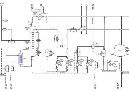
Piping and instrumentation diagram
A piping and instrumentation diagram (P&ID) is a detailed diagram in the process industry which shows the piping and process equipment together with the instrumentation and control devices.
Superordinate to the piping and instrumentation diagram is the process flow diagram (PFD) which indicates the more general flow of plant processes and the relationship between major equipment of a plant facility.
Contents and function


A piping and instrumentation diagram (P&ID) is defined by the Institute of Instrumentation and Control as follows:
- A diagram which shows the interconnection of process equipment and the instrumentation used to control the process. In the process industry, a standard set of symbols is used to prepare drawings of processes. The instrument symbols used in these drawings are generally based on International Society of Automation (ISA) Standard S5.1
- The primary schematic drawing used for laying out a process control installation.
They usually contain the following information:
- Mechanical equipment, including:
- Pressure vessels, columns, tanks, pumps, compressors, heat exchangers, furnaces, wellheads, fans, cooling towers, turbo-expanders, pig traps (see ‘symbols’ below)
- Bursting discs, restriction orifices, strainers and filters, steam traps, moisture traps, sight-glasses, silencers, flares and vents, flame arrestors, vortex breakers, eductors
- Process piping, sizes and identification, including:
- Pipe classes and piping line numbers
- Flow directions
- Interconnections references
- Permanent start-up, flush and bypass lines
- Pipelines and flowlines
- Blinds and spectacle blinds
- Insulation and heat tracing
- Process control instrumentation and designation (names, numbers, unique tag identifiers), including:
- Valves and their types and identifications (e.g. isolation, shutoff, relief and safety valves, valve interlocks)
- Control inputs and outputs (sensors and final elements, interlocks)
- Miscellaneous – vents, drains, flanges, special fittings, sampling lines, reducers and swages
- Interfaces for class changes
- Computer control system
- Identification of components and subsystems delivered by others
P&IDs are originally drawn up at the design stage from a combination of process flow sheet data, the mechanical process equipment design, and the instrumentation engineering design. During the design stage, the diagram also provides the basis for the development of system control schemes, allowing for further safety and operational investigations, such as a Hazard and operability study (HAZOP). To do this, it is critical to demonstrate the physical sequence of equipment and systems, as well as how these systems connect.
P&IDs also play a significant role in the maintenance and modification of the process after initial build. Modifications are red-penned onto the diagrams and are vital records of the current plant design.
They are also vital in enabling development of;
- Control and shutdown schemes
- Safety and regulatory requirements
- Start-up sequences
- Operational understanding.
P&IDs form the basis for the live mimic diagrams displayed on graphical user interfaces of large industrial control systems such as SCADA and distributed control systems.
Identification and reference designation
Based on STANDARD ANSI/ISA S5.1 and ISO 14617-6, the P&ID is used for the identification of measurements within the process. The identifications consist of up to 5 letters. The first identification letter is for the measured value, the second is a modifier, 3rd indicates passive/readout function, 4th – active/output function, and the 5th is the function modifier. This is followed by loop number, which is unique to that loop. For instance FIC045 means it is the Flow Indicating Controller in control loop 045. This is also known as the « tag » identifier of the field device, which is normally given to the location and function of the instrument. The same loop may have FT045 – which is the flow transmitter in the same loop.

For reference designation of any equipment in industrial systems the standard IEC 61346 (Industrial systems, installations and equipment and industrial products — Structuring principles and reference designations) can be applied. For the function Measurement the reference designator B is used, followed by the above listed letter for the measured variable.
For reference designation of any equipment in a power station the KKS Power Plant Classification System can be applied.
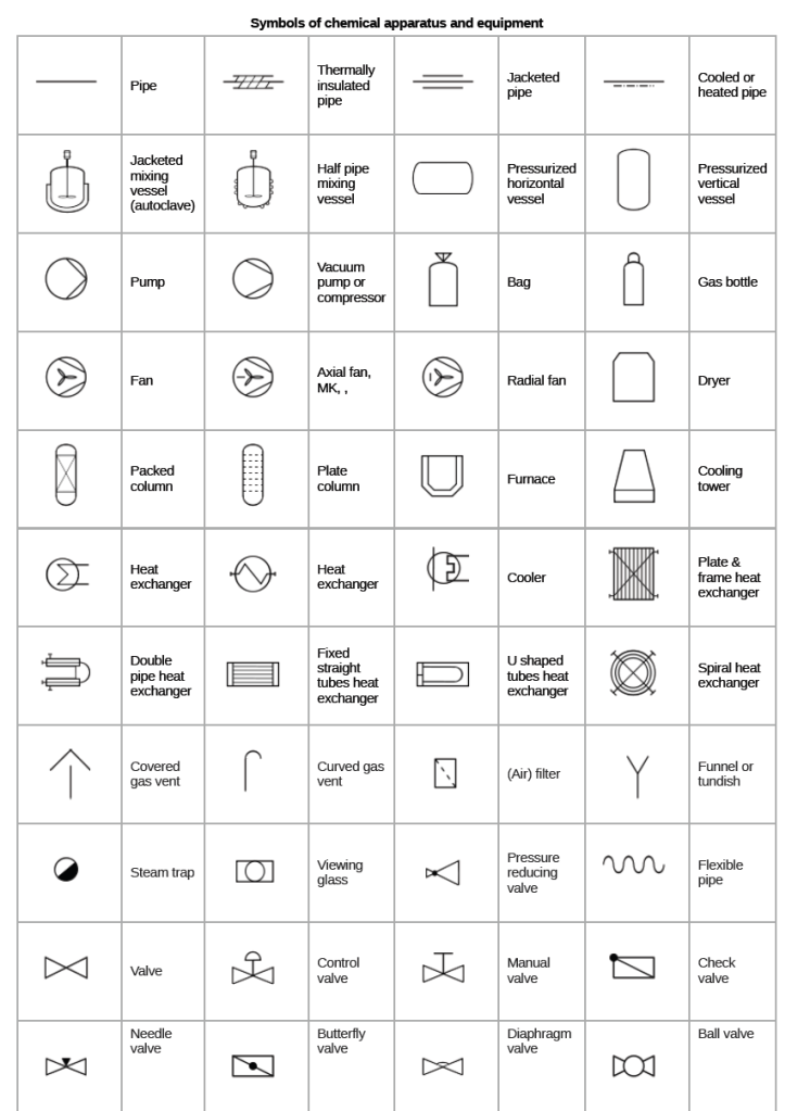
Symbols of chemical apparatus and equipment
Below are listed some symbols of chemical apparatus and equipment normally used in a P&ID, according to ISO 10628 and ISO 14617.
Deutsches Institut für Normung
From Wikipedia, the free encyclopedia (Redirected from DIN)Jump to navigationJump to search« DIN » redirects here. For other uses, see Din (disambiguation).
Deutsches Institut für Normung e.V. (DIN; in English, the German Institute for Standardization) is the German national organization for standardization and is the German ISO member body. DIN is a German Registered Association (e.V.) headquartered in Berlin. There are currently around thirty thousand DIN Standards, covering nearly every field of technology.
History
Founded in 1917 as the Normenausschuß der deutschen Industrie (NADI, « Standardisation Committee of German Industry »), the NADI was renamed Deutscher Normenausschuß (DNA, « German Standardisation Committee ») in 1926 to reflect that the organization now dealt with standardization issues in many fields; viz., not just for industrial products. In 1975 it was renamed again to Deutsches Institut für Normung, or ‘DIN’ and is recognized by the German[specify] government as the official national-standards body, representing German interests at the international and European levels.
The acronym, ‘DIN’ is often incorrectly expanded as Deutsche Industrienorm (« German Industry Standard »). This is largely due to the historic origin of the DIN as « NADI ». The NADI indeed published their standards as DI-Norm (Deutsche Industrienorm). For example, the first published standard was ‘DI-Norm 1‘ (about tapered pins) in 1918. Many people still mistakenly associate DIN with the old DI-Norm naming convention.
One of the earliest, and probably the best known, is DIN 476 — the standard that introduced the A-series paper sizes in 1922 — adopted in 1975 as International Standard ISO 216. Common examples in modern technology include DIN and mini-DIN connectors for electronics, and the DIN rail.
DIN standard designation
The designation of a DIN standard shows its origin (# denotes a number):
- DIN # is used for German standards with primarily domestic significance or designed as a first step toward international status. E DIN # is a draft standard and DIN V # is a preliminary standard.
- DIN EN # is used for the German edition of European standards.
- DIN ISO # is used for the German edition of ISO standards.
- DIN EN ISO # is used if the standard has also been adopted as a European standard.
Examples of DIN standards
- DIN 476: international paper sizes (now ISO 216 or DIN EN ISO 216)
- DIN 1451: typeface used by German railways and on traffic signs
- DIN 31635: transliteration of the Arabic language
- DIN 72552: electric terminal numbers in automobiles
International Organization for Standardization
The International Organization for Standardization (ISO; /ˈaɪsoʊ/) is an international standard-setting body composed of representatives from various national standards organizations.
Founded on 23 February 1947, the organization promotes worldwide proprietary, industrial and commercial standards. It is headquartered in Geneva, Switzerland, and works in 164 countries.
It was one of the first organizations granted general consultative status with the United Nations Economic and Social Council.
Consultative Status to the United Nations Economic and Social Council (ECOSOC) is the highest status granted by the United Nations to non-governmental organizations (NGO’s), thereby allowing them to participate in the work of the United Nations.
Overview
The International Organization for Standardization is an independent, non-governmental organization, the members of which are the standards organizations of the 164 member countries. It is the world’s largest developer of voluntary international standards and facilitates world trade by providing common standards between nations. Over twenty thousand standards have been set covering everything from manufactured products and technology to food safety, agriculture and healthcare.
Use of the standards aids in the creation of products and services that are safe, reliable and of good quality. The standards help businesses increase productivity while minimizing errors and waste. By enabling products from different markets to be directly compared, they facilitate companies in entering new markets and assist in the development of global trade on a fair basis. The standards also serve to safeguard consumers and the end-users of products and services, ensuring that certified products conform to the minimum standards set internationally.
Language usage
The three official languages of the ISO are English (with Oxford spelling), French, and Russian.
Name and abbreviations
The name of the organization in French is Organisation internationale de normalisation, and in Russian, Международная организация по стандартизации (Mezhdunarodnaya organizatsiya po standartizatsii). ISO is not an acronym. The organization adopted ISO as its abbreviated name in reference to the Greek word isos (ίσος, meaning « equal »), as its name in the three official languages would have different acronyms. During the founding meetings of the new organization, the Greek word explanation was not invoked, so this meaning may have been made public later.
ISO gives this explanation of the name: « Because ‘International Organization for Standardization’ would have different acronyms in different languages (IOS in English, OIN in French), our founders decided to give it the short form ISO. ISO is derived from the Greek isos, meaning equal. Whatever the country, whatever the language, the short form of our name is always ISO. »
Both the name ISO and the ISO logo are registered trademarks, and their use is restricted.
History
The organization today known as ISO began in 1928 as the International Federation of the National Standardizing Associations (ISA). It was suspended in 1942 during World War II, but after the war ISA was approached by the recently formed United Nations Standards Coordinating Committee (UNSCC) with a proposal to form a new global standards body. In October 1946, ISA and UNSCC delegates from 25 countries met in London and agreed to join forces to create the new International Organization for Standardization; the new organization officially began operations in February 1947.
Membership

Yellow: Correspondent members (countries without a national standards body).
Red: Subscriber members (countries with small economies).
ISO has 163 national members.
ISO has three membership categories:
- Member bodies are national bodies considered the most representative standards body in each country. These are the only members of ISO that have voting rights.
- Correspondent members are countries that do not have their own standards organization. These members are informed about ISO’s work, but do not participate in standards promulgation.
- Subscriber members are countries with small economies. They pay reduced membership fees, but can follow the development of standards.
Participating members are called « P » members, as opposed to observing members, who are called « O » members.
International standard
International standards are technical standards developed by international organizations (intergovernmental organizations), such as Codex Alimentarius in food, the World Health Organization Guidelines in health, or ITU Recommendations in ICT and being publicly funded, are freely available for consideration and use worldwide.
Purpose
International standards may be used either by direct application or by a process of modifying an international standard to suit local conditions. The adoption of international standards results in the creation of equivalent, national standards that are substantially the same as international standards in technical content, but may have (i) editorial differences as to appearance, use of symbols and measurement units, substitution of a point for a comma as the decimal marker, and (ii) differences resulting from conflicts in governmental regulations or industry-specific requirements caused by fundamental climatic, geographical, technological, or infrastructural factors, or the stringency of safety requirements that a given standard authority considers appropriate.
International standards are one way of overcoming technical barriers in international commerce caused by differences among technical regulations and standards developed independently and separately by each nation, national standards organization, or company. Technical barriers arise when different groups come together, each with a large user base, doing some well established thing that between them is mutually incompatible. Establishing international standards is one way of preventing or overcoming this problem.
American National Standards Institute
The American National Standards Institute (ANSI /ˈænsi/ AN-see) is a private non-profit organization that oversees the development of voluntary consensus standards for products, services, processes, systems, and personnel in the United States. The organization also coordinates U.S. standards with international standards so that American products can be used worldwide.
ANSI accredits standards that are developed by representatives of other standards organizations, government agencies, consumer groups, companies, and others. These standards ensure that the characteristics and performance of products are consistent, that people use the same definitions and terms, and that products are tested the same way. ANSI also accredits organizations that carry out product or personnel certification in accordance with requirements defined in international standards.
The organization’s headquarters are in Washington, D.C. ANSI’s operations office is located in New York City. The ANSI annual operating budget is funded by the sale of publications, membership dues and fees, accreditation services, fee-based programs, and international standards programs.
History
ANSI was originally formed in 1918, when five engineering societies and three government agencies founded the American Engineering Standards Committee (AESC). In 1928, the AESC became the American Standards Association (ASA). In 1966, the ASA was reorganized and became United States of America Standards Institute (USASI). The present name was adopted in 1969.
Prior to 1918, these five founding engineering societies:
- American Institute of Electrical Engineers (AIEE, now IEEE)
- American Society of Mechanical Engineers (ASME)
- American Society of Civil Engineers (ASCE)
- American Institute of Mining Engineers (AIME, now American Institute of Mining, Metallurgical, and Petroleum Engineers)
- American Society for Testing and Materials (now ASTM International)
had been members of the United Engineering Society (UES). At the behest of the AIEE, they invited the U.S. government Departments of War, Navy (combined in 1947 to become the Department of Defense or DOD) and Commerce to join in founding a national standards organization.
According to Adam Stanton, the first permanent secretary and head of staff in 1919, AESC started as an ambitious program and little else. Staff for the first year consisted of one executive, Clifford B. LePage, who was on loan from a founding member, ASME. An annual budget of $7,500 was provided by the founding bodies.
In 1931, the organization (renamed ASA in 1928) became affiliated with the U.S. National Committee of the International Electrotechnical Commission (IEC), which had been formed in 1904 to develop electrical and electronics standards.
Members
ANSI’s members are government agencies, organizations, academic and international bodies, and individuals. In total, the Institute represents the interests of more than 270,000 companies and organizations and 30 million professionals worldwide.
Process
Although ANSI itself does not develop standards, the Institute oversees the development and use of standards by accrediting the procedures of standards developing organizations. ANSI accreditation signifies that the procedures used by standards developing organizations meet the Institute’s requirements for openness, balance, consensus, and due process.
ANSI also designates specific standards as American National Standards, or ANS, when the Institute determines that the standards were developed in an environment that is equitable, accessible and responsive to the requirements of various stakeholders.
Voluntary consensus standards quicken the market acceptance of products while making clear how to improve the safety of those products for the protection of consumers. There are approximately 9,500 American National Standards that carry the ANSI designation.
The American National Standards process involves:
- consensus by a group that is open to representatives from all interested parties
- broad-based public review and comment on draft standards
- consideration of and response to comments
- incorporation of submitted changes that meet the same consensus requirements into a draft standard
- availability of an appeal by any participant alleging that these principles were not respected during the standards-development process.
United States Patent and Trademark Office
The United States Patent and Trademark Office (USPTO) is an agency in the U.S. Department of Commerce that issues patents to inventors and businesses for their inventions, and trademark registration for product and intellectual property identification.
The USPTO is « unique among federal agencies because it operates solely on fees collected by its users, and not on taxpayer dollars ». Its « operating structure is like a business in that it receives requests for services—applications for patents and trademark registrations—and charges fees projected to cover the cost of performing the services [it] provide[s] ».
The USPTO is based in Alexandria, Virginia, after a 2005 move from the Crystal City area of neighboring Arlington, Virginia. The offices under Patents and the Chief Information Officer that remained just outside the southern end of Crystal City completed moving to Randolph Square, a brand-new building in Shirlington Village, on April 27, 2009.
The current Under Secretary of Commerce for Intellectual Property and Director of the USPTO is Andrei Iancu. He began his role as Director on February 8, 2018. Iancu was nominated by President Trump in August 2017, and unanimously confirmed by the U.S. Senate. Prior to joining the USPTO, he was the Managing Partner at Irell & Manella LLP, where his practice focused on intellectual property litigation.
The USPTO cooperates with the European Patent Office (EPO) and the Japan Patent Office (JPO) as one of the Trilateral Patent Offices. The USPTO is also a Receiving Office, an International Searching Authority and an International Preliminary Examination Authority for international patent applications filed in accordance with the Patent Cooperation Treaty.

Mission
The USPTO maintains a permanent, interdisciplinary historical record of all U.S. patent applications in order to fulfill objectives outlined in the United States Constitution. The legal basis for the United States patent system is Article 1, Section 8, wherein the powers of Congress are defined.
It states, in part:
The Congress shall have Power … To promote the Progress of Science and useful Arts, by securing for limited Times to Authors and Inventors the exclusive Right to their respective Writings and Discoveries.
The PTO’s mission is to promote « industrial and technological progress in the United States and strengthen the national economy » by:
- Administering the laws relating to patents and trademarks;
- Advising the Secretary of Commerce, the President of the United States, and the administration on patent, trademark, and copyright protection; and
- Providing advice on the trade-related aspects of intellectual property.
Symbolic language (engineering)
In engineering, a symbolic language is a language that uses standard symbols, marks, and abbreviations to represent concepts such as entities, aspects, attributes, and relationships.[1][original research?]
Engineering symbolic language may be used for the specification, design, implementation, management, operation, and execution of engineered systems.
Communication using precise, concise representations of concepts is critical in engineering. The Nuclear Principles in Engineering book begins with a quote on symbolic language from Erich Fromm and its power to express and depict associations. The engineering employs symbolic language in a way that is not purely text-based and not purely image-based to represent and communicate knowledge.
Examples in chemical engineering include the symbolic languages developed for process flow diagrams and for piping and instrumentation diagrams (P&IDs).
in electrical engineering, examples include the symbolic languages developed for network diagrams used in computing.
Ladder logic was originally a written symbolic language for the design and construction of programmable logic control (PLC) operations in mechanical and control engineering.
International Society of Automation
The International Society of Automation (ISA), formerly known as The Instrumentation, Systems, and Automation Society, is a non-profit technical society for engineers, technicians, businesspeople, educators and students, who work, study or are interested in automation and pursuits related to it, such as instrumentation. It was originally known as the Instrument Society of America. The society is more commonly known by its acronym, ISA, and the society’s scope now includes many technical and engineering disciplines. ISA is one of the foremost professional organizations in the world for setting standards and educating industry professionals in automation. Instrumentation and automation are some of the key technologies involved in nearly all industrialized manufacturing. Modern industrial manufacturing is a complex interaction of numerous systems. Instrumentation provides regulation for these complex systems using many different measurement and control devices. Automation provides the programmable devices that permit greater flexibility in the operation of these complex manufacturing systems.
ISA provides leadership and education in the professions that it serves, assisting engineers, technicians, and research scientists, as well as many others, in keeping pace with the rapidly changing industry. ISA professionals work in numerous fields and may provide expertise in diverse areas ranging from environmental quality to automobile manufacturing, to nearly any technological field in use today. In recent years as the organization has modernized and broadened its scope, this has branched out to even more fields such as network security personnel, programmers, chemical engineers and more.
Structure
The International Society of Automation is a non-profit member-driven organization, which is built on a backbone of volunteers. Volunteers, working together with the ISA’s full-time staff of over 75, are key to the ongoing mission and success of the organization. The ISA has a strong leadership development program that develops volunteer leaders as they get involved with the organization’s many different facets. ISA has several different ways that volunteers get involved from the section, division, and standards roots of the organization.
ISA members are typically assigned an ISA Section (local chapter) which is related to their geographic location. Members can then join ISA Divisions which correspond to their individual technical interests. ISA Standards Committees are open to both ISA members and non-members to become involved with.
In addition to the member-driven aspects of the ISA, the organization itself is divided into departments headed by a director. These departments are:
- Education, Training & Publications
- Marketing & Graphics
- Membership
- IT
- Sales
- Standards
- Finance
- Customer/Member Service
Technical divisions
ISA’s 17 technical divisions, established for the purpose of increased information exchange within tightly focused segments of the fields of instrumentation, systems, and automation are organized under the Automation & Technology or Industries & Sciences Departments, depending upon the nature of the division.
The divisions in the Automation & Technology Department are :
- Analysis
- Automatic Control Systems
- Computer Technology
- Management
- Process Measurement & Control
- Robotics & Expert Systems
- Safety
- Telemetry & Communications
- Test Measurement
Industries & Sciences Divisions are:
- Aerospace Industries
- Chemical & Petroleum Industries
- Construction & Design
- Food & Pharmaceuticals Industries
- Mining & Metals Industries
- Power Industry
- Pulp & Paper Industries
- Water & Wastewater Industries
Standards
ISA standards play a major role in the work of instrumentation and automation professionals. Many ISA standards have been recognized by the American National Standards Institute (ANSI). Many ISA standards have also been adopted as international standards by the International Electrotechnical Commission (IEC).
ISA standards cover a wide range of concepts of importance to instrumentation and automation professionals. ISA has standards committees for symbols and nomenclature used within the industry, safety standards for equipment in non-hazardous and hazardous environments, communications standards to permit interoperable equipment availability from several manufacturers, and additional committees for standards on many more technical issues of importance to the industry. An example of one significant ISA standard is the ANSI/ISA-50.02 Fieldbus Standard for Use in Industrial Control Systems, which is a product of the ISA-50 Signal Compatibility of Electrical Instruments committee. Another significant ISA standard family is the batch processing standards of ANSI/ISA-88.00.01 Models and Terminology, ANSI/ISA-88.00.02 Data Structures and Guidelines for Languages, and ANSI/ISA-88.00.03 General and Site Recipe Models and Representation, which are products of the ISA-88 Batch Control committee.
Other standards developed by ISA include:
ISA100.11a is for testing and certification of wireless products and systems. This standard was approved by the International Electrotechnical Commission (IEC) as a publicly available specification, or PAS in September 2011.
ISA95 is an international standard for developing an automated interface between enterprise and control systems.
As of 2012, the Society has over 162 published standards, recommended practices, and technical reports.
IEC 61346
IEC 61346 is an electrotechnical standard titled « Industrial systems, Installations and Equipment and Industrial Products — Structuring Principles and Reference Designations« . It sets voluntary standards on how to structure systems and generate reference designations.
Contents
- Part 1: Basic rules (IEC 61346-1:1996)
- Part 2: Classification of objects and codes for classes (IEC 61346-2:2000)
- Part 3: Application guidelines (IEC/TR 61346-3:2001)
- Part 4: Discussion of concepts (IEC 61346-4:1998)
IEC standards have numbers in the range 60000–79999 while the numbers of older IEC standards were converted in 1997 by adding 60000. Thus the IEC 61346-1 was published as IEC 1346-1.
Future standards
Future developments of the standards on reference designations will be made in cooperation between the IEC and the ISO and published as IEC 81346. (Standards developed in cooperation between IEC and ISO are assigned numbers in the 80000 series)
Specification (technical standard)
A specification often refers to a set of documented requirements to be satisfied by a material, design, product, or service. A specification is often a type of technical standard.
There are different types of technical or engineering specifications (specs), and the term is used differently in different technical contexts. They often refer to particular documents, and/or particular information within them. The word specification is broadly defined as « to state explicitly or in detail » or « to be specific ».
Using the term « specification » without a clear indication of what kind is confusing and considered bad practice.
A requirement specification is a documented requirement, or set of documented requirements, to be satisfied by a given material, design, product, service, etc. It is a common early part of engineering design and product development processes, in many fields.
A functional specification is a kind of requirement specification, and may show functional block diagrams.
A design or product specification describes the features of the solutions for the Requirement Specification, referring to either a designed solution or final produced solution. It is often used to guide fabrication/production. Sometimes the term specification is here used in connection with a data sheet (or spec sheet), which may be confusing. A data sheet describes the technical characteristics of an item or product, often published by a manufacturer to help people choose or use the products. A data sheet is not a technical specification in the sense of informing how to produce.
An « in-service » or « maintained as » specification, specifies the conditions of a system or object after years of operation, including the effects of wear and maintenance (configuration changes).
Specifications are a type of technical standard that may be developed by any of various kinds of organizations, both public and private. Example organization types include a corporation, a consortium (a small group of corporations), a trade association (an industry-wide group of corporations), a national government (including its military, regulatory agencies, and national laboratories and institutes), a professional association (society), a purpose-made standards organization such as ISO, or vendor-neutral developed generic requirements. It is common for one organization to refer to (reference, call out, cite) the standards of another. Voluntary standards may become mandatory if adopted by a government or business contract.
Use
In engineering, manufacturing, and business, it is vital for suppliers, purchasers, and users of materials, products, or services to understand and agree upon all requirements.
A specification may refer to a standard which is often referenced by a contract or procurement document, or an otherwise agreed upon set of requirements (though still often used in the singular). In any case, it provides the necessary details about the specific requirements.
Standards for specifications may be provided by government agencies, standards organizations (SAE, AWS, NIST, ASTM, ISO, CEN, DoD, etc.), trade associations, corporations, and others. The following British standards apply to specifications:
- BS 7373-1:2001 Guide to the preparation of specifications
- BS 7373-2:2001 Product specifications. Guide to identifying criteria for a product specification and to declaring product conformity
- BS 7373-3:2005, Product specifications. Guide to identifying criteria for specifying a service offering
A design/product specification does not necessarily prove a product to be correct or useful in every context. An item might be verified to comply with a specification or stamped with a specification number: this does not, by itself, indicate that the item is fit for other, non-validated uses. The people who use the item (engineers, trade unions, etc.) or specify the item (building codes, government, industry, etc.) have the responsibility to consider the choice of available specifications, specify the correct one, enforce compliance, and use the item correctly. Validation of suitability is necessary.
Guidance and content
Sometimes a guide or a standard operating procedure is available to help write and format a good specification. A specification might include:
- Descriptive title, number, identifier, etc. of the specification
- Date of last effective revision and revision designation
- A logo or trademark to indicate the document copyright, ownership and origin
- Table of Contents (TOC), if the document is long
- Person, office, or agency responsible for questions on the specification, updates, and deviations.
- The significance, scope or importance of the specification and its intended use.
- Terminology, definitions and abbreviations to clarify the meanings of the specification
- Test methods for measuring all specified characteristics
- Material requirements: physical, mechanical, electrical, chemical, etc. Targets and tolerances.
- Acceptance testing, including Performance testing requirements. Targets and tolerances.
- Drawings, photographs, or technical illustrations
- Workmanship
- Certifications required.
- Safety considerations and requirements
- Environmental considerations and requirements
- Quality control requirements, acceptance sampling, inspections, acceptance criteria
- Person, office, or agency responsible for enforcement of the specification.
- Completion and delivery.
- Provisions for rejection, reinspection, rehearing, corrective measures
- References and citations for which any instructions in the content maybe required to fulfill the traceability and clarity of the document
- Signatures of approval, if necessary
- Change record to summarize the chronological development, revision and completion if the document is to be circulated internally
- Annexes and Appendices that are expand details, add clarification, or offer options.
Food and drug specifications
Pharmaceutical products can usually be tested and qualified by various Pharmacopoeia. Current existing pharmaceutical standards include:
- British Pharmacopoeia
- European Pharmacopoeia
- Japanese Pharmacopoeia
- The International Pharmacopoeia
- United States Pharmacopeia
If any pharmaceutical product is not covered by the above standards, it can be evaluated by the additional source of Pharmacopoeia from other nations, from industrial specifications, or from a standardized formulary such as
A similar approach is adopted by the food manufacturing, of which Codex Alimentarius ranks the highest standards, followed by regional and national standards.
The coverage of food and drug standards by ISO is currently less fruitful and not yet put forward as an urgent agenda due to the tight restrictions of regional or national constitution.
Specifications and other standards can be externally imposed as discussed above, but also internal manufacturing and quality specifications. These exist not only for the food or pharmaceutical product but also for the processing machinery, quality processes, packaging, logistics (cold chain), etc. and are exemplified by ISO 14134 and ISO 15609.
The converse of explicit statement of specifications is a process for dealing with observations that are out-of-specification. The United States Food and Drug Administration has published a non-binding recommendation that addresses just this point.
At the present time, much of the information and regulations concerning food and food products remain in a form which makes it difficult to apply automated information processing, storage and transmission methods and techniques.
Data systems that can process, store and transfer information about food and food products need formal specifications for the representations of data about food and food products in order to operate effectively and efficiently.
Development of formal specifications for food and drug data with the necessary and sufficient clarity and precision for use specifically by digital computing systems have begun to emerge from some government agencies and standards organizations: the United States Food and Drug Administration has published specifications for a « Structured Product Label » which drug manufacturers must by mandate use to submit electronically the information on a drug label. Recently, the ISO has made some progress in the area of food and drug standards and formal specifications for data about regulated substances through the publication of ISO 11238.
Information technology
Specification need
In many contexts, particularly software, specifications are needed to avoid errors due to lack of compatibility, for instance, in interoperability issues.
For instance, when two applications share Unicode data, but use different normal forms or use them incorrectly, in an incompatible way or without sharing a minimum set of interoperability specification, errors and data loss can result. For example, Mac OS X has many components that prefer or require only decomposed characters (thus decomposed-only Unicode encoded with UTF-8 is also known as « UTF8-MAC »). In one specific instance, the combination of OS X errors handling composed characters, and the samba file- and printer-sharing software (which replaces decomposed letters with composed ones when copying file names), has led to confusing and data-destroying interoperability problems.
Applications may avoid such errors by preserving input code points, and only normalizing them to the application’s preferred normal form for internal use.
Such errors may also be avoided with algorithms normalizing both strings before any binary comparison.
However errors due to file name encoding incompatibilities have always existed, due to a lack of minimum set of common specification between software hoped to be inter-operable between various file system drivers, operating systems, network protocols, and thousands of software packages.
Formal specification
A formal specification is a mathematical description of software or hardware that may be used to develop an implementation. It describes what the system should do, not (necessarily) how the system should do it. Given such a specification, it is possible to use formal verification techniques to demonstrate that a candidate system design is correct with respect to that specification. This has the advantage that incorrect candidate system designs can be revised before a major investment has been made in actually implementing the design. An alternative approach is to use provably correct refinement steps to transform a specification into a design, and ultimately into an actual implementation, that is correct by construction.
Architectural specification
In (hardware, software, or enterprise) systems development, an architectural specification is the set of documentation that describes the structure, behavior, and more views of that system.
Program specification
A program specification is the definition of what a computer program is expected to do. It can be informal, in which case it can be considered as a user manual from a developer point of view, or formal, in which case it has a definite meaning defined in mathematical or programmatic terms. In practice, many successful specifications are written to understand and fine-tune applications that were already well-developed, although safety-critical software systems are often carefully specified prior to application development. Specifications are most important for external interfaces that must remain stable.
Functional specification
In software development, a functional specification (also, functional spec or specs or functional specifications document (FSD)) is the set of documentation that describes the behavior of a computer program or larger software system. The documentation typically describes various inputs that can be provided to the software system and how the system responds to those inputs.
Web service specification
Web services specifications are often under the umbrella of a quality management system.
Document specification
These types of documents define how a specific document should be written, which may include, but is not limited to, the systems of a document naming, version, layout, referencing, structuring, appearance, language, copyright, hierarchy or format, etc. Very often, this kind of specifications is complemented by a designated template.
Process flowsheeting
Process flowsheeting is the use of computer aids to perform steady-state heat and mass balancing, sizing and costing calculations for a chemical process. It is an essential and core component of process design.
The process design effort may be split into three basic steps
Synthesis
Synthesis is the step where the structure of the flowsheet is chosen. It is also in this step that one initializes values for variables which one is free to set.
Analysis
Analysis is usually made up of three steps
- Solving heat and material balances
- Sizing and costing the equipment and
- Evaluating the economic worth, safety, operability etc. of the chosen flow sheet
Optimization
Optimization involves both structural optimization of the flow sheet itself as well as optimization of parameters in a given flowsheet. In the former one may alter the equipment used and/or its connections with other equipment. In the later one can change the values of parameters such as temperature and pressure. Parameter Optimization is a more advanced stage of theory than process flowsheet optimization.
Plant design project
The first step in the sequence leading to the construction of a process plant and its use in the manufacture of a product is the conception of a process. The concept is embodied in the form of a « flow sheet ». Process design then proceeds on the basis of the flow sheet chosen. Physical property data are the other component needed for process design apart from a flow sheet. The result of process design is a process flow diagram, PFD. Detailed engineering for the project and vessel specifications then begin. Process flowsheeting ends at the point of generation of a suitable PFD.
General purpose flowsheeting programs became usable and reliable around 1965-1970.
