
Lire et créer des schémas de procédés de type PID
Piping and Instrumentation Diagrams (P&IDs) use specific symbols to show the connectivity of equipment, sensors, and valves in a control system. These symbols can represent actuators, sensors, and controllers and may be apparent in most, if not all, system diagrams. P&IDs provide more detail than a process flow diagram with the exception of the parameters, i.e. temperature, pressure, and flow values. “Process equipment, valves, instruments and pipe lines are tagged with unique identification codes, set up according to their size, material fluid contents, method of connection (screwed, flanged, etc.) and the status (Valves – Normally Closed, Normally Open).” These two diagrams can be used to connect the parameters with the control system to develop a complete working process. The standard notation, varying from letters to figures, is important for engineers to understand because it a common language used for discussing plants in the industrial world.
P&IDs can be created by hand or computer. Common programs, for both PC and Mac, that create P&IDs include Microsoft Visio (PC) and OmniGraffle (Mac). As with other P&IDs, these programs do not show the actual size and position of the equipment, sensors and valves, but rather provide a relative positions. These programs are beneficial to produce clean and neat P&IDs that can be stored and viewed electronically. See below for P&ID templates for these programs.
This section covers four main types of nomenclature. The first section describes the use of lines to describe process connectivity. The second section describes letters used to identify control devices in a process. The third section describes actuators, which are devices that directly control the process. The final section describes the sensors/transmitters that measure parameters in a system.
Here is some information about PID:
A List of P&ID items
- Instrumentation and designations
- Mechanical equipment with names and numbers
- All valves and their identifications
- Process piping, sizes and identification
- Miscellanea – vents, drains, special fittings,sampling lines, reducers, increasers and swagers
- Permanent start-up and flush lines
- Flow directions
- Interconnections references
- Control inputs and outputs, interlocks
- Interfaces for class changes
- Computer control system input
- Identification of components and subsystems delivered by others
A good P&ID should include:
- Instrumentation and designations
- Mechanical equipment with names and numbers
- All valves and their identifications
- Process piping, sizes and identification
- Miscellaneous – vents, drains, special fittings, sampling lines, reducers, increasers and swagers
- Permanent start-up and flush lines
- Flow directions
- Interconnections references
- Control inputs and outputs, interlocks
- Interfaces for class changes
- Seismic category
- Quality level
- Annunciation inputs
- Computer control system input
- Vendor and contractor interfaces
- Identification of components and subsystems delivered by others
- Intended physical sequence of the equipment
- Equipment rating or capacity
A P&ID should not include:
- Instrument root valves
- control relays
- manual switches
- primary instrument tubing and valves
- pressure temperature and flow data
- elbow, tees and similar standard fittings
- extensive explanatory notes
Line Symbols
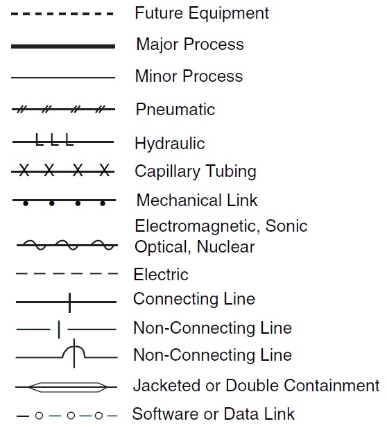
Line symbols are used to describe connectivity between different units in a controlled system. The table describes the most common lines.

In Table table above, the “main process” refers to a pipe carrying a chemical. “Insulated” is straightforward, showing that the pipe has insulation. “Trace heated” shows that the pipe has wiring wrapped around it to keep the contents heated. “Lagged” indicates on a P&ID that the pipe is wrapped in a cloth or fiberglass wrap as an alternative to painting to improve the appearance of the pipe. The last column in the Table shows pipes that are controlled by a controller. “Electrical impulse” shows that the manner in which information is sent from the controller to the the pipe is by an electrical signal, whereas “pneumatic impulse” indicates information sent by a gas.
In addition to line symbols, there are also line labels that are short codes that convey further properties of that line. These short codes consist of: diameter of pipe, service, material, and insulation. The diameter of the pipe is presented in inches. The service is what is being carried in the pipe, and is usually the major component in the stream. The material tells you what the that section of pipe is made out of. Examples are CS for carbon steel or SS for stainless steel. Finally a ‘Y’ designates a line with insulation and an ‘N’ designates one without it. Examples of line short codes on a P&ID are found in the figure below.

This is useful for providing you more practical information on a given pipe segment.
For example in stream 39 in Figure above, the pipe has a 4″ diameter, services/carries the chemical denoted ‘N’, is made of carbon steel, and has no insulation.
Instrumentation identification letters
The following letters are used to describe the control devices involved in a process. Each device is labeled with two letters. The first letter describes the parameter the device is intended to control. The second letter describes the type of control device.
| First Letter | Measurement |
| A | Analysis |
| B | Burner, Combustion |
| C | User’s Choice (usually Conductivity) |
| D | User’s Choice (usually Density) |
| E | Voltage |
| F | Flow |
| G | User’s Choice |
| H | Hand |
| I | Current |
| J | Power |
| K | Time, Time Schedule |
| L | Level |
| M | User’s Choice |
| N | User’s Choice (usually Torque) |
| O | User’s Choice |
| P | Pressure |
| Q | Quantity |
| R | Radiation |
| S | Speed, Frequency |
| T | Temperature |
| U | User’s Choice (usually Alarm Output) |
| V | Vibration, Mechanical Analysis |
| W | Weight, Force |
| X | User’s Choice (usually on-off valve as XV) |
| Y | Event, State, Presence |
| Z | Position, Dimension |
| Second Letter | Type of Control Device |
| A | Alarm |
| C | Control |
| I | Indicator |
| T | Transmit |
| V | Valve |
For example, the symbol “FI,” is a “Flow indicator.”
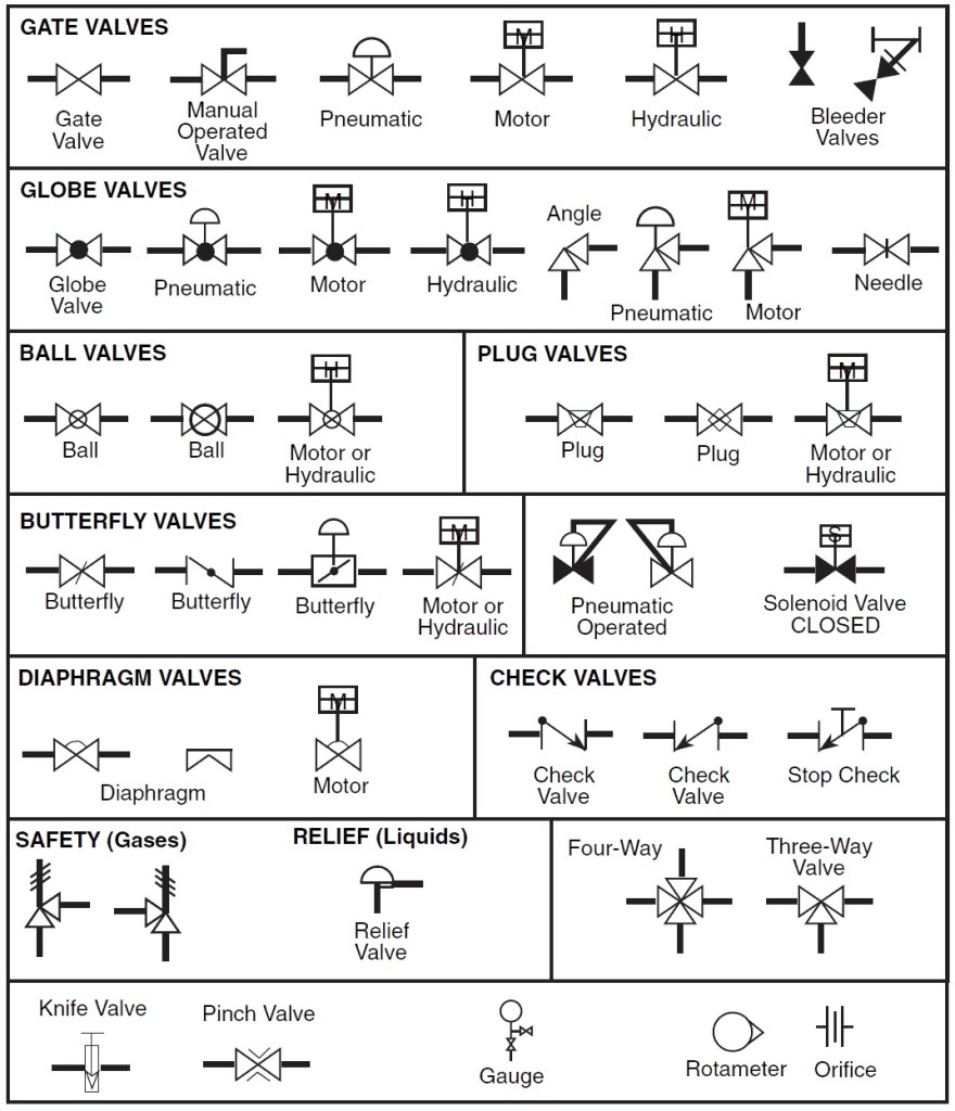
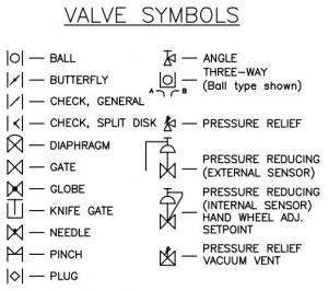
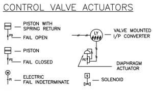
Valve Symbols
The following symbols are used to represent valves and valve actuators in a chemical engineering process. Actuators are the mechanisms that activate process control equipment.


En tant qu’ingénieur process vous aurez forcement besoin un jour ou l’autre de créer ou consulter un PID. Mais qu’est ce que c’est ? Alors non, PID n’est pas l’acronyme de Proportional, Integrative et Derivative, pour ce qui concerne les boucle de contrôle. PID est l’acronyme de Piping and Instrumentation Diagram.
Le PID est un PFD très complet car il reprend tous les équipements, avec toute l’instrumentation associée mais aussi les numéros de lignes leur diamètre et aussi les lignes nécessaires au démarrage ou aux arrêts… Le PID est l’un des documents les plus complets que vous pourrez trouver dans l’ingénierie pour avoir une vision globale d’une unité. Il est tout de même préférable d’utiliser dans un premier temps un PFD afin de bien comprendre le fonctionnement d’une unité pour ensuite trouver plus de détails dans le PID. La lecture d’un PID est complexe et c’est pourquoi il faut savoir le lire !
1. Le cartouche
Dans un premier temps, il faut repérer le cartouche, un rectangle en bas à droite. Il permet de connaître la partie de l’unité qu’il représente, qui l’a fait, à quelle date mais aussi combien l’unité en question comporte de PID.
2. La légende
Dans un second temps, très souvent, le premier PID sert à présenter les différentes figures et symboles qui seront utilisés. Il est important de l’avoir à coté car les représentations d’une check valve n’est pas la même si vous travaillez dans le domaine du pétrole ou dans celui de la chimie.
Voici un exemple de légende concernant les vannes (source edraw).

Cette légende montre bien qu’il y a une multitude de représentation de vanne aussi il est important d’avoir cette légende aussi bien pour faire que lire un PID.
Ici, c’est un exemple de vanne, mais il y a la même chose sur les indicateurs d’instrument, les équipements, les différents signaux… A vous d’utiliser ceux qui correspondent aux us et coutumes de votre milieu !
3. Lecture d’un PID
Prenons l’exemple de la localisation d’une vanne de contrôle de l’équipement 1 sur l’unité B.
Dans un premier temps il faut à l’aide du cartouche repérer si l’on est dans la bonne unité. Ensuite il faudra trouver l’équipement 1 puis touver si la vanne de contrôle mesure une entrée ou une sortie. Le plus simple est de partir d’un gros équipement puis ensuite d’affiner la recherche.
4. Faire un PID
Il faut tout de suite penser qu’un PID devient vite complet et donc il faut mettre entre 1 et 3 équipements dessus au maximum sinon il peut vite devenir illisible. En sachant ça, vous serez en mesure de déterminer combien il vous faudra en faire et ensuite ajuster votre numérotation de PID.
Placez les équipements sur le PID en faisant en sorte qu’ils soient bien placés (pas trop près des bords et dans le sens de la lecture). Regarder la Datasheet de l’équipement en question pour qu’il y ait une bonne cohérence (nombre et nom des nozzles, proportions de l’équipement…).
Reliez-les ensuite avec les lignes process de fonctionnement normales puis mettez les boucles de contrôles nécessaires (vanne et instruments).
Ensuite il convient de placer l’instrumentation locale et celle qui ira en salle de contrôle.
Une fois ces opérations réalisées, il faut mettre tous les équipements nécessaires à la maintenance (vanne de bloc autour des vannes de contrôle, drains, évents…), au démarrage (ligne de remplissage, bac de remplissage…) et d’arrêt mais aussi de sécurité (Pressure Safety Valve…).
Ces étapes réalisées, vous pourrez ensuite mettre la numérotation des lignes, leurs diamètres et la numérotation des instruments.
Bien sur chaque PID est unique et correspond à une philosophie bien particulière seulement tout ingénieur process doit-être en mesure de le lire car il est le document le plus complet de l’unité !!!
Learn How to Read P&ID Drawings – A Complete Guide
In this article and video, I have tried to answer the question “How to Read P&ID”.
Reading P&ID is a difficult task for those who start their careers in Oil &Gas and similar Chemical Process Industries. Here, I have tried to explain P&ID and PEFS an easy way.
The piping and instrumentation diagram is also known as the Process engineering flow scheme which is PEFS.
You will learn how to read P&ID and PEFS with the help of the actual plant drawing. P&ID is more complex than of PFD and includes lots of details. Link to download this P&ID is given at the end of the page.
Watch the video as it has step by step line tracing to have a better understanding on the topic.
What is P&ID?
P&ID is a graphical representation of the actual process plant using various symbols that represent actual equipment. As said earlier it is complex than PFD. A single PFD can have multiple P&ID. This means if some system is shown on single PFD, to show the same system on P&ID, it may require multiple P&ID sheets.
It is one of the main deliverables of FEED. That is front-end engineering and design. It is used during the entire life-cycle of the plant. That means during pre-EPC, EPC and operation.
Use of P&ID/PEFS During Pre- EPC Phase
P&ID is used to derive the Project capital cost estimates. It is also used to develop EPC contract specifications. Plot plant is developed considering various inputs from P&ID and physical site location.
Use of P&ID/PEFS during the EPC phase
During the EPC phase, P&ID is used to develop the individual unit layout. It used to identify hazardous areas classification, preparing data sheets of equipment, valves, and instrument.
P&ID is used to develop the piping layout and preparing bulk material take-off for piping, electrical, instrumentation and civil. It is key documents for various reviews such as HAZOP, SIL and operability review.
During Operation, you have to maintain P&ID in such a condition that it will show actual plant conditions at any time. It should be updated when any physical change is made so that the unit will remain compliant with codes, standards, and specification, and can be operated safely under the defined process conditions.
P&IDs are used to train operators and engineers before they start work in the plant.
What information does P&ID provide?
- All the equipment, including installed spares, and associated piping including drain and vent line.
- Insulation or jacketing requirements.
- Instrumentation
- Heat tracing and insulation detail
- Information about utilities
- Piping components including their size, class and tag Number
- Information required for design, construction, and operation such as
- A slope of the line
- Minimum and maximum distance from the equipment or instruments
- Minimum straight lengths after instruments
What is not included in a P&ID?
- Process conditions and physical data
- Operating conditions
- Streamflow details
- Equipment locations
- Pipe routing, length, and fittings
- Support and structural details are also not included in p&id
Ok, now you know what P&ID is and types of information you’re going to get from the drawing. Let’s confirm this with the help of actual P&ID.
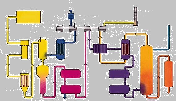
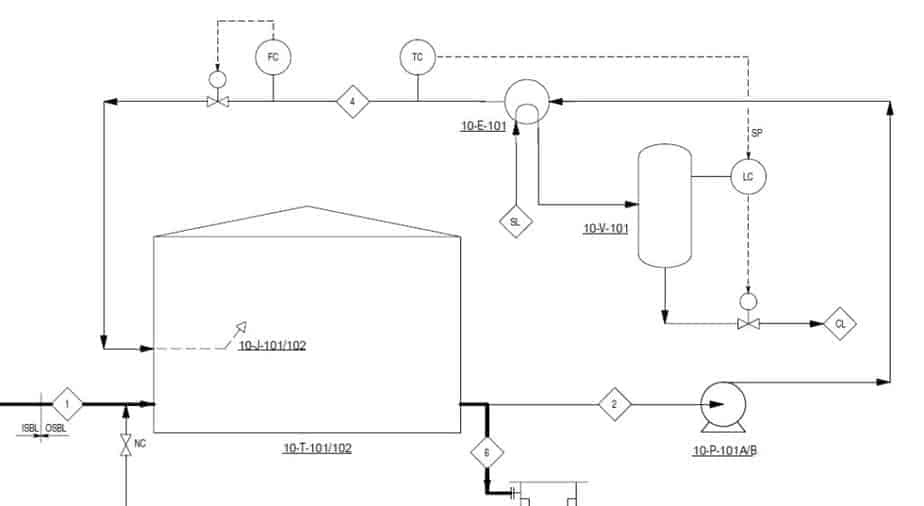
This is a PFD of the flushing oil system that shows the entire system of pump seal flushing oil. This is the simplest system with just one cone roof tank and two centrifugal pumps. The pump used in a heavier product such as crude, fuel oil required flushing oil to keep the pump seal clean. Here Ultra-low sulfur diesel is used as flushing oil.
You can see here that ULSD is coming from diesel rundown line to the tank and with the help of pump it is supplied to the various pump of ISBL and OSBL units’.
I hope the function of the system is clear to you. Now let’s move to P&ID.
There are two P&IDs for the OSBL part of this system and may more for ISBL parts. I will explain to you the OSBL part of the system.
Reading P&ID is nothing but the reading of symbols. So, if you have not seen the earlier videos on P&ID symbols and how to read PFD, it will be difficult for you to understand this drawing. You can watch these videos.
How to Read PFD
How to Read P&ID
If possible, get a print of this P&ID in A3 and follow the video. You can download this P&ID the link is given at the end of the article.
It is always a good practice to start reading P&ID from the main incoming lines and follow the fluid path.
Line Tracing – Mani Incoming Line
Here ATF is coming from CDU; you can see that. Remember the blackhead on the arrow? You have learned this in how to read the PFD video. It means Diesel is coming from a different unit. Here you can see the line number. It is a 150 mm diameter line as per DN standard which is equivalent to 6” NPS.
The different company follows different terminology for the line number. But it contains same information such as line size, unit number, commodity code that identify fluid inside the line, circuit number, line sequence number, piping class that gives all detail about piping components and their materials, insulation, and coating requirement.
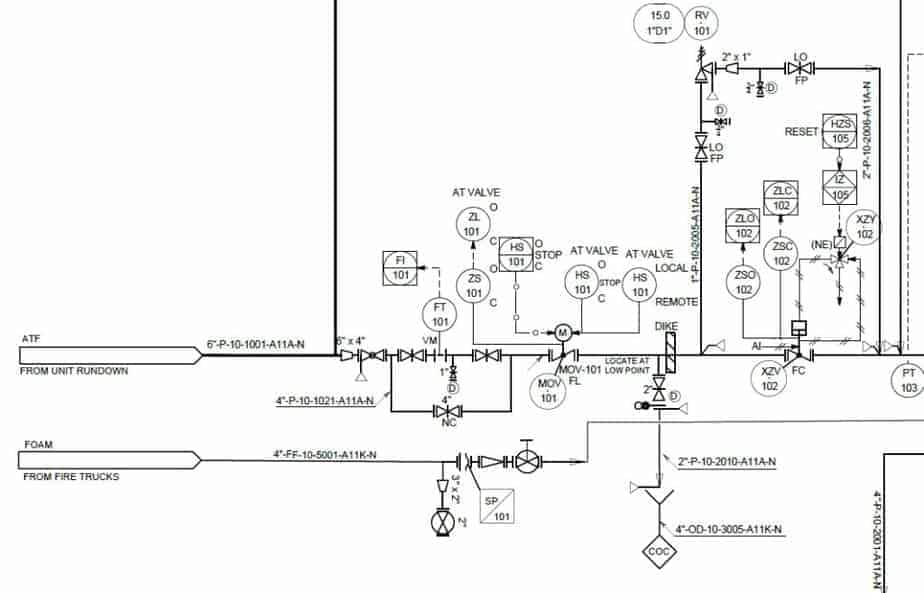
Here N means there is no insulation. If there is H than hot insulation, C is for cold insulation, A for acoustic reduction, P for personal protection, F for fireproofing. It also gives information about whether the line is steam trace or electric trace. Normally ET is used for electric tracing and ST is used for steam tracing.
Let’s move ahead, here you can see that the diesel line is divided into two strim. We follow this strim. 6” line is getting reduced to 4”. Don’t get confused with reducer symbol; it is just an indication of line size change. In piping, it can be a reducing tee as it is 6” to 4” concentric reduction.
Now, this triangle with line indicates a line break. A line break is the demarcation of the line number change. So, whenever this symbol is used it indicates that from that point onward line number is different.
This is the bypass loop for the flow transmitter. You can see that the venturi-type flow transmitter provided in between the two gate valves. Why did I say it is a venture type flow transmitter? Letters VM indicates the type of flow transmitter. It gives flow indication on the control plane. You can see the connection shown between FT and FI.
From the piping point of view, you can see that there is a 25 mm drain valve is given in between the two gate valves. The letter D indicates that it is a drain valve and if it is V than it is a vent valve. Of course, if it is a vent, it shows on the topside, not on the bottom. The bypass valve is also a gate valve that will remain closed during normal operation. You can see the letters NC which indicates the same.
MOV Symbols
Reading P&ID is nothing but reading P&ID symbols. So, if you are aware of symbols, you can easily understand the P&ID. Here you can see the motor-operated butterfly valve. Lots of instruments are shown here. But it is not that complicated. If you are aware of MOV, you know that it can be operated locally or from the control penal. You can read the AT VALVE label that means this instrument function is available on the valve itself.
HS indicates hand switch, with these switches you can put MOV on manual control or remote control that means on panel control. You can also start or stop the valve from the field. HS-O means open, and HS-C means close. The data link indicates this valve is connected to the control panel.
The last two instrument bubbles show the potions of the valve. From the field, you can set and see the % of the valve opening.

Next is a drain valve that is located at the lowest point. This is the spectacle blind with a normally closed configuration. If the dark ring is towards the valve, as in this case, it indicates that solid ring covers and isolates the joint during normal operation.
If the only circle is towards the valve, as shown here, that means the hollow ring is there, and the line is live during the normal operation.
Below the drain valve, the funnel is shown. So, when you drain ATF it will go to the COC system. COC means continues oil-contaminated that used to drain hydrocarbon. The second type of drain is AOC that means an accidentally oil-contaminated system.
After a dike wall, there is a pneumatically controlled globe valve is there. You can see the pneumatic line symbol. Like MOV, the pneumatic valve also has various switches to operate the valve locally and from the control panel. You can also see the three-way valve connected to the pneumatic line to operate the actuator.
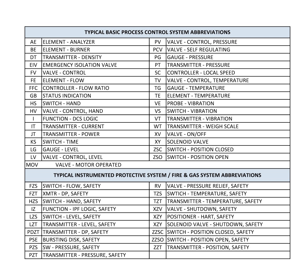
You can refer to the abbreviation table to understand the meaning of all these instrument bubbles. I have attached this table with a free download. The link is given in the description.
P&ID Abbreviation Table

You can see that there is a relief valve in bypass. It used to protect the actuator from the surge.
Main Equipment – Tank
Next is a tank. First, I will explain mechanical parts and then instrumentation. As you can see, this is a fixed roof tank. On top of the P&ID, you can see the detail of each of the equipment shown in the drawing. Let see the detail of this tank.
The tank is 17.5 meters in height with an 8.25-meter diameter. You can also see the operating pressure and temperature of the tank. The material of construction is carbon steel, and there is no insulation. Now let go back to the tank.
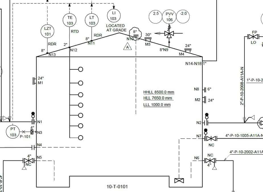
N1 to N17 are nozzle numbers. P&ID doesn’t show the exact location of the nozzle, but it shows the size of the nozzle. Manholes are shown as M1 to M3. The broken line shows the internal piping. There is a vortex breaker with the N8 nozzle connected to a pump suction line with a Normally Closed gate valve. This is because the main suction line is N2. N8 will use only when you want to drain the tank completely.
There are two more nozzle N9 and N10 that used to drain the tank to COC. This is open type liquid seals that prevent air ingress into the tank.
Now let’s check the instrumentation. For safe operation of any equipment, you have to monitor pressure, temperature, and level. Here you can see the Pressure Transmitter near the tank bottom plate. On top of the roof, you can see the radar type level indicator and transmitter.
The temperature gauge is shown as TE that is temperature elements. This arrangement shows multiple thermocouples installed at a different height of the tank. This will ensure that you will get an average temperature of the tank as the liquid has a different temperature at a different level.
What is LLL, HLL, and HHLL in Tanks and Equipment?
LZT is a level safety transmitter. Here you can see the value for LLL, HLL, and HHLL. LLL means low liquid level, HLL means high liquid level and HHLL means high high liquid level. LLL protects your pump and when tank level reached to LLL, it gave the alarm in control penal and based on the logic configuration it may trigger to switch off command to the pump.
HLL and HHLL will use to protect the tank from overfilling. When the liquid level reached the HLL it gives the alarm and when it reached HHLL it will trigger the safety logic and stop the fluid supply to the tank.
There is a breather valve on the tank. It will protect the tank from the overpressure and vacuum.
Now, these all instrument bubbles are sending the information to the local and main control panel for the pressure, level and temperature instrument that I have explained to you. You may have noticed that there is a tank gauging system which received the all input signal from the instruments.
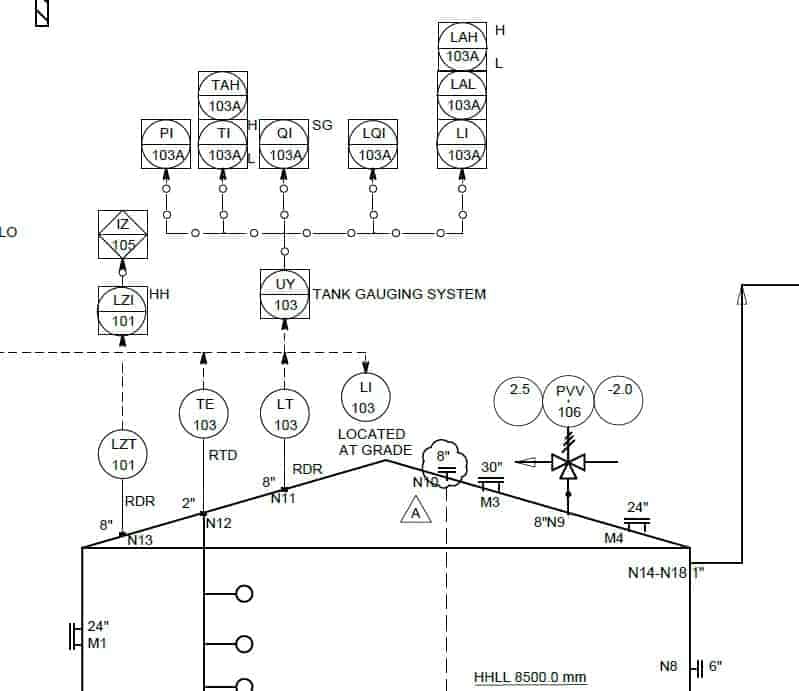
The tank gauging system is used to calculate the quantity of the liquid stored in the tank at any given time. Based on the diameter, level, and temperature it will calculate the quantity of the liquid stored in the tank. QI is a quantity indicator.
In the last part of this video, let check what is going out of the tank. AFT from the tank is supplied to the pump with the help of 150 mm pipeline. You can see that inside dike there is a manual gate valve with a bypass arrangement. There is a safety relief valve on the bypass.
Outside the dike, you can see the motor-operated butterfly valve. This MOV has similar switches that I have explained to you earlier to operate the valve locally and from the control panel.
If you know the instrument legends and symbols, you can read and understand any P&ID.
What is Process Flow Diagram and Read It Like Pro – A Complete Guide
Process Flow Diagram (PFD) which is also known as Process Flow Chart, Process Flow sheets and Process flow scheme. In this article, you will learn what is this drawing is and what type of information is provided in it with the help of real plant PFD example.
What is Process Flow Diagram?
Process Flow Diagram (PFD) is a simple drawing that shows the relationships between major equipment in a process plant using equipment symbols and shows the primary process flow path of a unit. You can visualize the flow of material within the plant with the help of these drawing.
What is the use of Process Flow Diagram?
A process flow diagram provides a quick overview of the entire operating unit or a system. A technician or engineer can use this document to trace the flow of materials through the unit. The flow diagram is also used for visitor information and new employee training.
It is one of the core documents to draw the Plot Plant and P&ID.
What information does Process Flow Diagram provide?
A typical PFD will include:
- All Major equipment: Each equipment shown on PFD has a unique equipment number and a descriptive name. It also indicates main dimensions, capacity and operating information of the equipment.
- 2nd is – Process flow stream or interconnected piping. PFD follows left-right approach for process flow. That means any process stream enter or exit either from the right or left. However please note that this left-right approach is not a mandatory requirement but good engineering practice.
- All process flow streams shown on PFD will have an identification number. A description of the process conditions and the chemical composition of each stream such as pressure, temperature, density, mass flow rate, and a mass-energy balance will be included in PFD. These data will be either displayed directly on the PFD or included in the flow summary table. Sometimes, it also shows minimum, normal and maximum values of these process parameters. Next is
- The process flow direction of all process line
- Control valves and process-critical valves
- Major bypass and recirculation systems
- Connections with other systems
What is not included in a PFD?
- Pipe classes and pipeline numbers
- Process control instruments
- Minor bypass valves
- Isolation and shutoff valves
- Maintenance vents and drains
- Relief valves and safety valves and
- Code class information
You must be thinking if this information is not here than where they are? Well! This information is covered in P&ID which is more complex drawing than PFD.
To read PFD, PFS, P&ID, PEFS, iso and GA drawing, knowing the various symbols for equipment, valve, and the instruments is a must. So if you have not watched the earlier video on P&ID/PFD symbols, please watch that video first.
I will explain to you how to read this PFD or PFS with the help of the real drawing. Check the PFD that you are going to learn.
If you don’t want to read, watch this video which will explain to you all aspects covered in this article.
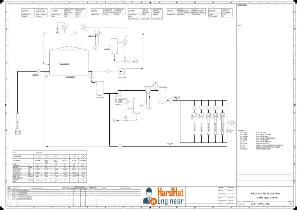
Now look at this PFS or PFD, well both are same. You can see the PFS of OSBL part of plant fuel oil and slop tank.
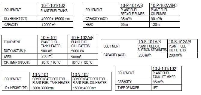
Equipment list on Process Flow Diagram
Let’s check the equipment that are used in this system. Here you can see the tank, pumps, exchanger, vessel, strainer and jet mixture. On top of any PFD, you can see the list of all the major equipment along with its size and capacity.
Lines in PFD
All the main process lines are shown as a dark black line, and the thin black lines are minor process lines. Aero heads on the line show the direction of the flow.
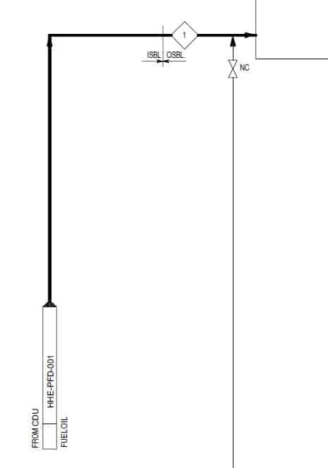
Fuel oil is coming from other ISBL units. You can see the incoming aero with a dark head. If there is no dark head and simple aero is there like this, it means the line is coming from the same unit.
You can see the battery limit between OSBL and ISBL. This process stream is numbered as one for which details are given in the table below. Square box with a number inside will give you the process stream number. Square box with letters inside means it refers to other service and for the detail of that stream you to refer to the PFD of that process. Here SL means steam line and the CL means condensate line.
This is a generic symbol of the valve. If you want to know the exact type of valve, you have to check the P&ID. The letters NC means Normally close. That means this valve remains closed during normal operation.
Tank Section
Now look at this loop, this is circulation loop. Fuel oil from the tank is supplied to pump which will pass through the heat exchanger and return to the tank. You have to maintain the temperature of the fuel otherwise it will get thick and chock the line and also settled in the tank.
You can see that there are two control valves are shown in this loop. One will maintain the temperature by controlling steam and the second one will maintain the flow. The symbol of the valve is a generic symbol of the remotely actuated valve. It can be the hydraulic, pneumatic or motor operated type.
If you are interested in learning more about valves and their function, you can buy my full course on the valve in which I have covered more than 18 types of valve. Yes, this is marketing because that is how I earn money to produce good quality videos and articles. So please support by purchasing my courses.
Now back to our PFD.
Pump Section of PFD
See this detail of the pump, recycle pump has a head of 60 meters and plant fuel oil pump has a head of 216 meters. These must be large pumps. Let’s look where they are in PFD.
Let me adjust the PFD on the screen so that we can conclude our video.
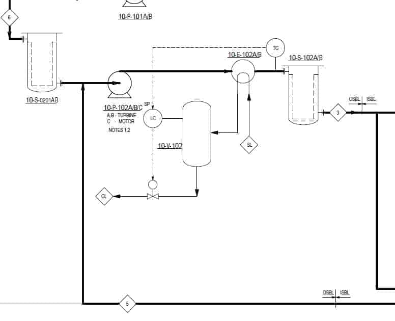
Ooh!! These pumps are turbine driven that means these are critical pumps. Normally turbine driven pumps are provided where you want to run the pump even if there is a total power failure in your plant.
Here we have two basket strainers one on the suction side and other on the pump discharge side, and we also have a heat exchanger to maintain the temperature of fuel oil.
The suction strainer will protect pump impeller from any foreign object that can damage the pump and discharge strainer will ensure clean supply to user units.
You can see the temperature control loop also.
Here, you can see the battery limits of ISBL and OSBL. Fuel oil is supplied to various ISBL unit’s furnaces. On ISBL side you can see that one pressure control valve is given which ensure constant pressure in the Fuel Oil loop.
Now let’s look at the stream table. Lots of process parameters such as pressure, temperature, flow rate, and other details are given in this table. Have a look at it.
This is all about PFD. You have learned all most all detail that PFD provides. If you want to learn about how to read P&ID, you can check the P&ID article here: https://hardhatengineer.com/how-to-read-pid-pefs-drawings/
P&ID and PFD Drawing Symbols and Legend list (PFS & PEFS)
P&ID and PFD Drawing used various Symbols and Legend.
If you want to learn how to read P&ID and PFD, you must know the legend used in this drawings. So please watch the video till the end. You can download this presentation for free. The link is available in description.
PFD and P&ID are also known as PFS and PEFS. PFD is Process Flow Diagram. P&ID is Process or piping & Instrument Diagram. PFS means Process Flow Scheme and PEFS means Process Engineering Flow Scheme.
Here, I have tried to cover symbols that regularly used on the P&ID and PFD. There are other symbols also you can check the full list of the symbol by visiting this link (https://www.lucidchart.com/pages/p-id-symbols-legend). I advised you before you start working on actual plant or construction project you should check the project-specific symbol library which is also known as P&ID lead sheets or P&ID legend drawing.
P&ID symbols and level of information available on P&ID may change from company to company, but more or less they provide similar information.
What P&ID or PFD symbol is?
P&ID symbols are a graphical representation of physical equipment that installed on the field.
There are few ISO and British standards available that provide symbols and best practices to draw PFD and P&ID such as, ISA S5.1, BS 5070 and ISO 10628.
https://hardhatengineer.com/what-is-the-difference-between-code-standard-and-specification/
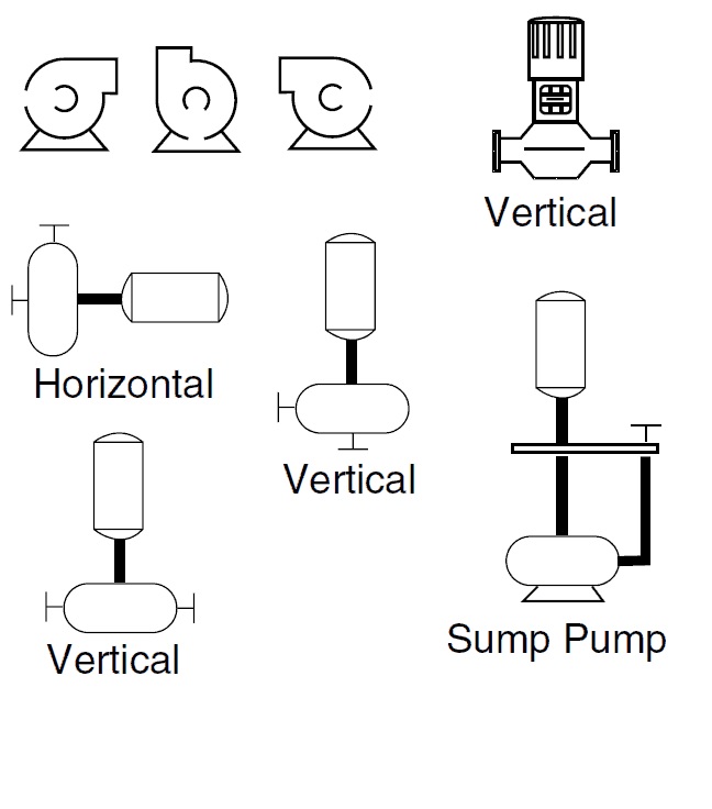
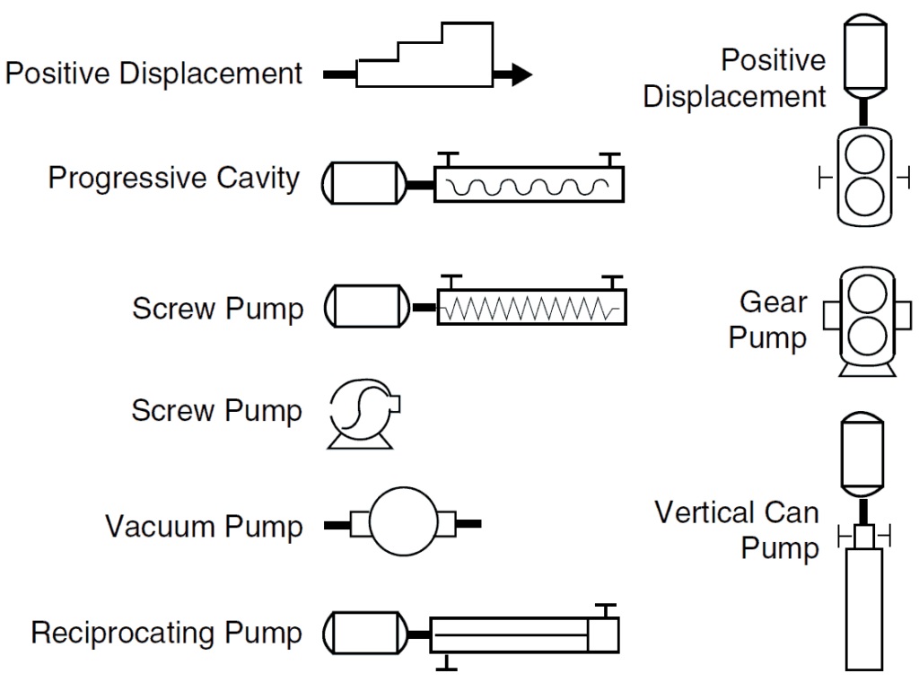
Pumps and Turbine P&ID Symbols
The symbols for various types of rotary equipment such as a centrifugal pump, vacuum pump and also positive displacement pumps such as gear and screw types. Last two symbols are of vertical pump and turbine.
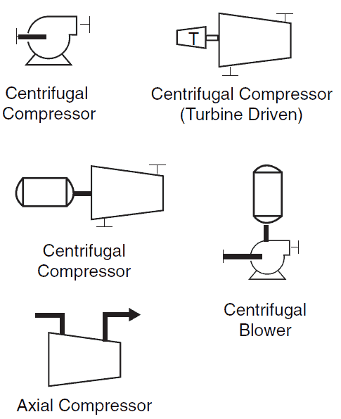
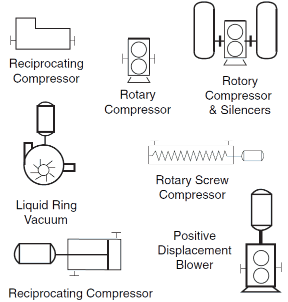
P&ID Symbols for Compressor
The symbols for the compressor such as reciprocating, centrifugal, rotary, liquid ring, and turbine driven.
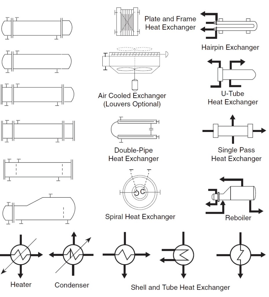
Heat Exchanger P&ID symbol
These are the symbols for the heat exchanger. On drawing you can see both types of symbols are used the one on the right-hand side are more frequent than the one on the left-hand side.
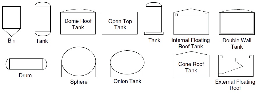
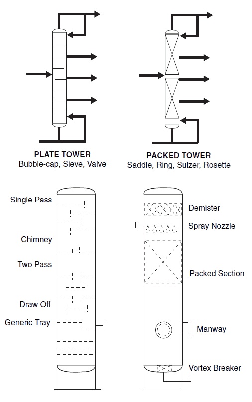
Symbols for Static Equipment and Distillation column
Static equipment are straightforward. Vessel, drum, tanks, and furnace. Here you can see the symbols for dome roof tank, fixed roof tank, and internal floating roof tank. In case of the tank is only floating roof than there will be no roof on this symbol.
There are two types of the tower are shown here, one with column internal, and the other is without internals. There are different types of internals are used in the column and for that different symbols are used.
Here in the distillation tower, you can see the different types of internal, such mist mat, pipe distributor, liquid spray distributor, vortex breaker, baffle plate, packing bed and some other types of trays.
Line Symbols for PFD and P&ID
Below image shows various lines and connections that used on PFD and P&ID. Main process lines are shown as dark black line whereas minor lines are shown as thin black lines. You can see the symbols for pneumatic, hydraulic and capillary lines also.
Electric signals are shown as a dotted line, and Electromagnetic signals are shown as a wave on the solid line.
P&ID Symbols for Piping Valves
This is the trickiest part of reading P&ID and PFD. Here you can see the various types of valve symbols. If you remember that I have mentioned that P&ID symbols vary from company to company, valves symbols are the one that changes most of the time. So, if you are moving from one company to other, don’t rely on your memory and refer the lead sheets for symbols. Lead sheets are the one that contains all the project or plant-specific symbols.
Symbols for instruments
Now back to our symbols. Here you can see the various instrument bubble. In a process plant, more than 90 percent of instrument measured either pressure, temperature, flow or level. You can see the small table on the side which shows the first letter of the instrument. Now the function of these instruments are either indicate, record, control or transmit the measured value.
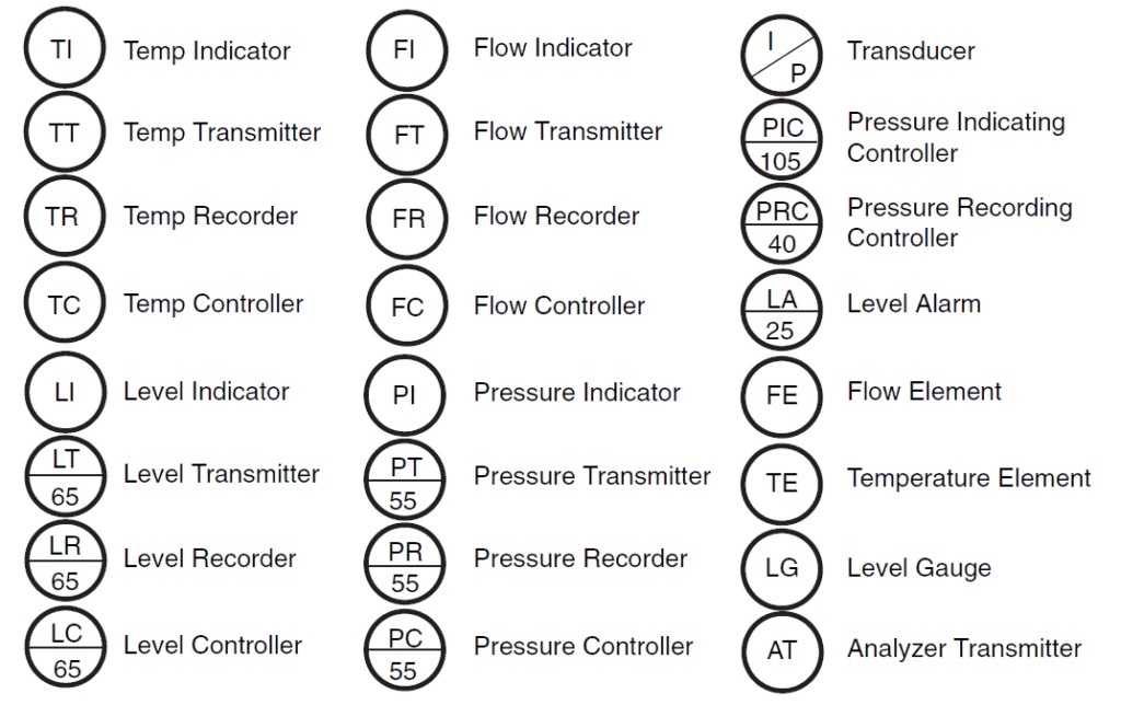
Here on this table, you can see the meaning of the first letter and subsequent letters. You can hold the video to read all the letters and their meaning. In next slide, I will tell you the meaning of the horizontal line on the instrument bubble.
| FIRST-LETTER | SECOND-LETTERS | ||||
|---|---|---|---|---|---|
| Measured or Initiating variable | Modifier | Readout function | Output function | Modifier | |
| A | Analysis | ||||
| C | Control | ||||
| D | Differential | ||||
| F | Flow Rate | Ratio | |||
| H | Hand | High | |||
| I | Current | Indicate | |||
| L | Level | Low | |||
| P | Pressure, vacuum | ||||
| Q | Quantity | Totalizer | |||
| R | Recorder | ||||
| S | Safety | Switch | |||
| T | Temperature | Transmit | |||
| V | Vibration | Valve, Damper | |||
| Z | Position | Actuator |
Showing 1 to 15 of 15 entries
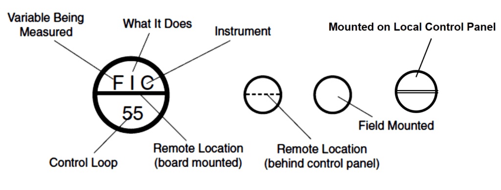
- If there is a single horizontal line that means the instrument is located on the main control panel and accessible to panel operator.
- No horizontal line means the instrument is installed in the field, near the process and it is accessible to field operator.
- If there is a double horizontal line that means the instrument is installed on some secondary satellite local panel in the field.
- The last type is instrument bubble with a single dashed horizontal line. This symbol is used for instruments that are inaccessible in field or hidden or password protected on the control system.
Check this link if you want to learn P&ID Symbology in extreme depth:
https://www.aiche.org/chenected/2010/09/interpreting-piping-and-instrumentation-diagrams-symbology
Click on link to Download the P&ID Symbols List:
https://hardhatengineer.com/?attachment_id=1307
Download the Presentation Symbols List by Click the link.
Articles by Robert COOK ON AICHE.ORG in five parts.
With a Bit of Smoke, a Few Mirrors and a Degree in Hieroglyphics, Anyone Can Learn to Read a P&ID. This is Part 1 of a five-part series.
Part 1 – Introduction

Engineers love to draw. Not necessarily in an artistic sense of the word, although beauty is, as they say, in the eye of the beholder. As for me, well, I’ve never been accused of having a particular gift in the arts, or photography for that matter (see bio mug shot taken in my natural habitat), but I have done a few process drawings in my 25? years as a process engineer. I guess that’s earned me my vice, VP of Engineering and Technology Development to be precise. Hi there. I’m Bob Cook and I’m glad to have you along for my premier entry here on ChEnected.com where we explore the interpretation of Piping and Instrumentation Diagrams, or P&IDs for those in the know. This is a topic that can benefit process, project and design engineers, business developers, operators, safety, maintenance and even management. Wow, that a lot of folks! However, consider this – all of the members listed above will either come across P&IDs intermittently or have to work with them as a core aspect of their job. And if I still have your attention then, yes, you too should have a solid understanding of how to read them! Hey you hiding the back…don’t be bashful. You say that you are two, three…five years out of school and still not sure you really have a good handle on P&IDs? You’re not alone. Having worked for many companies and provided services to a variety of industries over the years, I find it curious how P&IDs are often poorly understood by those who should know them better. In some cases, they exude this aura of intimidating, complex documents that only ChE geeks (and the like) really know how to read. I believe this is simply due to a dearth of formal training. Folks are just expected to pick it up « on the fly ». Given the variability in career direction our backgrounds in the best engineering field afford us, this works well for some but leaves others playing catch-up later on. So even experienced engineers and operators may one day discover their lack of knowledge on the topic puts them at a disadvantage. So let’s just put a stop to all that by taking P&IDs apart in this multi-part series.

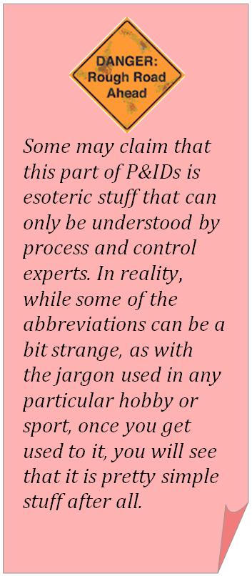
Regardless of experience level, you will find many of the symbols are obvious. Others need a bit more explanation. In much the same way ancient Egyptians used hieroglyphics thousands of years ago, we process folks (in conjunction with our peers in the electrical, controls and other departments) just come up with our own set of symbols to represent the various equipment, devices and control concepts that go into our plants. When you look at it that way, one could argue that not much has changed in a few thousand years. I suppose that’s true. Hey, if it isn’t broke, why fix it? Enough of my bantering, let’s get started already. I look forward to a healthy exchange. Part 2 will dig into P&IDs – The Fundamentals. I’ll include a few example drawings that we can use as we venture forth down that path of process knowledge. If you want to get a head start, download them here. Stay tuned!
Part 2 – The Fundamentals
In Part 1 of this series, I talked about why a solid understanding of P&ID interpretation is important to virtually every discipline involved in a process plant – from process engineering and detail design through construction, commissioning/start-up, operations and management. I’m glad to see I sold you on that point and welcome you back to part two of this saga. Things are starting to heat up and soon we will be weeding out the true process engineers from the causal posers who would rather go off and waste time browsing reddit or digg (which I never do by the way). We still have a bit of the academic stuff to cover before we really dig in but it’s important stuff so sit up straight and pay attention! Let’s kick things off by defining what P&IDs are and the types of information they illustrate. Afterwards, we’ll cover some of their limitations. It’s important to know the limitations of a tool so that you don’t apply it in the wrong way. At the end of Part 1, I provided a link to some example drawings that I put together to help illustrate some of the concepts I plan to discuss in this series. If you haven’t downloaded it yet, please do so now. The file contains:
- Two typical P&ID « Lead Sheets », and
- A few example P&ID drawings
A Word about Lead Sheets
We will talk more about the lead sheets (sometimes referred to as legend sheets) in Part 3 – Symbology. If you’ve never encountered lead sheets before, for now, just know that lead sheets are used to define the equipment and device symbols, tags and other notations, abbreviations and sometimes esoteric conventions that companies use to develop P&IDs for any project they execute. If you compare lead sheets from a few dozen companies, you will find that 90% of them are pretty much Copy | Paste. For that last 10%?, there can be distinct differences and company-specific conventions used that are not obvious on P&IDs. Therefore, it is good to know where the lead sheets are in your company so you can quickly track down the meaning of that pipe service label or some other obscure symbol.
The Example P&IDs
The last three drawings in the download link include some fairly typical P&IDs. I plan to use these in some upcoming videos to illustrate how the symbols from the lead sheets are applied to a real drawing and then compare that drawing to actual pictures of real-world plants. This will help forge the cognitive connection from the abstract realm of cubicle dwellers at CAD stations to the real world of process plants in action! Even if you are completely new to P&IDs, I’m sure there are some aspects that are obvious to you in these example drawings – things like the equipment and valve symbols, tags, etc. If not, that’s OK too because we will get into the details later but for now, just look them over and familiarize yourself with what’s there.
What are P&IDs?

A P&ID (or engineering flow drawing, EFD) is a type of process engineering drawing that describes all process design aspects of a plant. In this context, « Process Design » means all the stuff that makes up a plant, including:
- Major and minor equipment – the distinction between what is « major » vs. what is « minor » equipment is subjective
- Valves, including vents, bleeders, safety relief, sample (all of them!)
- Instrumentation, including devices that are used to continuously measure pressure, flowrate, massrate, temperature or some analyzed parameter such as pH, concentration, viscosity…the list goes on.
- Stand-alone controllers that may function independently to perform a particular function, like a PID controller or relay timer.
- Buttons used to control motors and devices, be they pushbutton, toggle, or some other type.
- Motors and drives – many motors are single speed, non-reversing but there are other kinds that have variable speed drives, and can operate in both directions.
- Limit and point devices – including devices that only reveal a discrete state, e.g., if a tank is at a certain level (point level), or a valve or actuator is in a particular position (a limit switch)
- That’s it…just kidding.
- Piping (of course!). All the pipes, tubes and even overflows in the plant. Not just the main process pipes inherent to the particular process, but even the utilities (steam, air, fuel, etc.).
- Virtual devices on computer control screens (often as graphical representations real-world objects) that are used to interact with the plant from the control room/panel. This includes things like « clickable » buttons used to start/stop equipment, operate valves, adjust controller settings, setpoint sliders and dials, evaluate alarms, etc. Computer functions and software « links » are generally limited because it is difficult to convey complete control meaning using just symbols. However, it doesn’t matter if the process is running on a home-brew Excel VBA project with Dick-and-Jane graphics or a state-of-the-art Honeywell DCS – the symbology used to represent the control interface will be shown.
I probably forgot some stuff in the list above but you get the idea. Clearly there can be a lot of information to show on a P&ID. And for this reason, there are various degrees of detail that a particular company will generally choose to show. There is no formal standard for the various amounts of information a P&ID must include. Rather, it is left to the discretion of the engineers involved. In terms of detail provided, my opinion is that a good P&ID will strike a balance of « clarity without confusion ». If you can’t see the process for all the symbols, then it’s probably overdone. On the other hand, if you can’t even discern how a pump may be operated or what interlocks may exist, then you probably need to embellish it a bit.
P&ID Support Documents
For those things that are deliberately left off P&IDs for the sake of clarity, other documents are used to provide the details. Common documents that serve vital support functions to P&IDs include:
- Process Flow Drawings (PFDs) are simple flow drawings that illustrate the general plant streams, major equipment and key control loops. They also provide detailed mass/energy balance data along with stream composition and physical properties. P&IDs originate from PFDs.
- Piping and material specifications. Here, you can dig into all the gory details about materials of construction, gaskets, bolts, fittings, etc. for each of the services. (I will talk about this more in a future post.)
- Equipment and instrumentation specifications. Modern CAD software used to produce P&IDs are sometimes called « smart » because they can incorporate specifications, standards and details that go into the design. Yea, they are cool but just as you can’t fix stupid, you can’t see « smart ». Thus, it’s good to have tangible documents that folks can access and digest outside the masters of CAD.
- Functional/process control documents that describe in detail, how the plant operates. A good one will include preferred standards for use on control screens/displays. Folks involved in programming the computers used to operate the plant need these.
How Should P&IDs be Organized?
Now you know what a P&ID is and what goes on them but you’re not quite ready for the corner office. At this point it’s worth considering how a set of P&IDs can (and should) be organized for a particular process.
There is no single good answer to this question and most companies will have a defined precedent or standard that they follow but if you find yourself at File | New with nothing to go on, because you just started your own company and (whoa…dude I just realized there is no mechanical group anymore) my advice is to keep in mind that when you set out to develop a set of P&IDs you are essentially writing a structured document, not unlike a book or report with chapters/sections and a logical progression. OK, a really boring book with no plot or characters, but you get the idea! My point is, you should plan the structure and break the task down into manageable sections based on area in the plant, function and other criteria that might be of importance to the project/process. Here’s a quick example. Consider a process plant with that receives raw feedstock in a storage area, feeds them into some reactor train(s) to make some product and then includes a storage and packaging back end. This particular process might be sitting inside a larger complex and leveraging existing utility infrastructure and tank farms. In this case, you might elect to break the P&IDs down as such:
- Raw material receiving and storage
- Process trains for product manufacture
- Product storage and packaging
- Tie-ins to facility utilities and distribution
- Environmental controsl and specialty unit operations/vendor packages such as thermal fluid, complex unit operations, etc.
Breaking a set of P&IDs down into logical sections makes the drawing set easier to develop, digest and, perhaps most importantly – change. Any of you that have tampered with object-oriented programming should be nodding in agreement at this point. Once you have the categorical areas broken down, the drawing set is then linked together via arrows and notations. Ultimately, it all fits together to like a puzzle to yield a continuous masterpiece.

Some companies like to develop their P&IDs so that if you had a huge wall, you could tape them together and all of the various interconnecting arrows would line up as the parts of a jigsaw puzzle. I have found that such an approach places unreasonable restrictions on the convenient location of equipment and arrows and generally doesn’t afford any greater understanding of the holistic process. It’s not uncommon for even relatively simple processes to have a dozen or more P&IDs so you would need a really big wall and then you wouldn’t be able to read anything without getting close. My advice is to make efficient use of the space provided, use the interconnect arrows as required to link them together and not get caught up on how well they align with the god of geometric continuity (I think that was a Greek god, not sure).
What are P&IDs Used For?
P&IDs really do have vital roles. In fact, if I had to pare it down to the top two, this is my list:
- Act as the definition of the process from which all engineering, fabrication, construction and operation is based.
- Serve as reference for Process Safety Information (PSI) in Process Safety Management (PSM).
To effectively accomplish these objectives, a good set of P&IDs should do the following:
- Provide a clear and concise illustration of all equipment, pipes, valves, instruments, sensors, etc. so that anyone involved has a solid understanding of the process.
- Provide information to assist in analyzing process hazards, safeguards and potential faults so that all kinds of errors (design, human/operation, etc.) are minimized, ideally eliminated.
- Support development of operating and maintenance procedures.
- Serve as an as-built record of the process so that changes can be planned safely and effectively using Management of Change (MOC).
So it’s pretty clear that the P&IDs define the process at a root level. They serve as the foundation upon which the system is designed, built and operated. Anyone who tells you that they can design a plant without first generating P&IDs either is a Deity or has endless funds that they enjoy throwing at poorly executed projects during the construction+ phases.
P&ID Limitations
At this point, you might be wondering what P&IDs can’t do. After all, so far we’ve painted a picture that they have seeming supernatural powers. Well, there are a few things that P&IDs don’t do well and it’s important that you know what these are so that nobody makes any false assumptions because we all know what happens when one assumes.
Despite their illustrious superhero status in the process engineering world, there are a couple things P&IDs don’t do well. Let’s get it out in the open now:
- They don’t reveal scale or geometry,
- They don’t serve as a true model for how things are oriented and placed in the real world.
Like I said in the intro to this series, I’ve been doing process engineering for 150 years (in the snow, uphill to work both ways) and I still run into instances where somebody will base a decision on how to make a change or try to find something in the plant based on where or how it looks on the P&ID. Here’s a ProTip – a better way to get a handle on where things really are at in the field is to use the P&IDs as a guide and do a walk-down or find other scale drawings. Good examples of true scale drawings are the ones used by contractors to build the plant. These include civil and piping plans, sections and/or isometrics, skid/equipment fabrication drawings, instrument location plans, etc. If you just assume that a pipe is located somewhere because it looks that way on the P&ID, you might be disappointed! Since we’re exposing the superman P&IDs to a bit of kryptonite, let’s review some other weaknesses of P&IDs just to make sure we’ve covered all the key points:
- Not to Scale – as stated above, P&IDs can’t be relied on as a scale guide for where pipes, equipment or other items are in proximity to equipment in the real world. Yes, I’m repeating that again because it will be on the quiz.
- Not Geometrically Accurate – P&IDs don’t illustrate geometry. The level of detail that goes into symbols for equipment will vary, but is almost never geometrically correct!
- Color Blind – P&IDs are not good at using color to convey meaning. While the folks who draw them often use color to help spot things on a monitor, don’t try too hard to glean meaning from color printouts or you may just end up seeing stars…
- Not Definitive – P&IDs do not include complete specs for all of the equipment in the process. They are, after all drawings, not documents. If you need details, grab the pertinent data sheets or vendor specs. Or ask someone for some help.
- Not Drawn Consistently – Sadly, P&IDs seldom look consistent between companies. That’s because there is a lot of flexibility in how one can go about drawing a P&ID (due to various standards, CAD systems, etc.) and that leaves them open to company and/or personal preferences. As a result, P&IDs often take on a different « look and feel » from company-to-company or even from job-to-job inside the same company. This can be a point of confusion when you get used to a certain way of seeing them. But don’t sweat it; just reorient yourself to the ways and means used by the process tribe in your group. Did you just think about lead sheets! Bonus point for you!
OK, so now you have a solid feel for what P&IDs are, the purposes they serve and their limitations. Hopefully, you’ve taken the time to at least glance at the example drawings provided. Great, in Part 3 of this series we will dig into the symbology used so we can interpret the geek speak of process engineers!
Part 3 – Symbology Primer
Welcome back to Part 3 folks! Let me apologize at the outset for the delay in getting this posted sooner but we had our Labor Day holiday here in the USA last week and oddly enough, we tend NOT to work on Labor Day. Go figure… I suppose it should be called slacker day because I really didn’t do much the whole weekend. In any event, I’m back in the saddle so let’s recap the last two parts before we hit the trail again. We have a lot of ground to cover before sunset.
- Part 1 talked about why the interpretation of P&IDs is important to everyone involved in the planning, design, and construction through operation of a process plant.
- Part 2 described the various functions P&IDs serve and highlighted the kinds of information they convey, along with the support documents that are commonly associated with them. We also talked about some of their weaknesses.
With the requisite academics out of the way, it’s time to focus on the exciting stuff – P&ID symbology interpretation. That’s the goal I had when I started this series and by golly, I’m sticking to it. However, I’m going to warn you up front – this is a big part in the series, figuratively and literally speaking. I might even be pushing the limits of Chenected.com‘s server capacity but I did my best to balance breadth of content with depth of detail. If you think I short-changed any areas and would like more detail on any topic, please let me know via the comment system. I’ll do my best to oblige.
Lead Sheets Define Symbology
As I mentioned in Part 2, the meanings of the various symbols used on P&IDs (aka, symbology) are defined on separate drawings called « Lead Sheets » (or Legend Sheets). These are your « secret decoder rings » to P&ID symbology interpretation. Every company that builds process plants should have a set of lead sheets customized to their particular ways and means. Having seen a number of lead sheets over the years, I can tell you that most of them are just variations on a core set of generally accepted symbols and notations that engineers and industry organizations have settled on as defacto standards over the years. The lead sheets I provide in the supporting file download to this series include the following;
- D001 – Instrumentation and Valves
- D002 – Codes, Tags, and Labels
Here’s the good news – these lead sheets include 90.00?0.05% of what you need to know. Seriously, the significant digits are right here, I checked them. Yeah, I realize some companies have more than two lead sheets, four or five even. Probably even a few with six or seven just to prove a point I suppose, but the number of lead sheets isn’t important. What is important is that they are logically organized so that the symbols and tags can be located easily. Poorly organized and/or incomplete lead sheets will just frustrate folks who turn to them for help so it’s important to keep them neat, concise and logical. And the two I present here should be up-front-and-center in your set. Related to the content I include on the example lead sheets, you might have noticed a conspicuous absence of lead sheets for major equipment, i.e., tanks, pumps, and sundry items typically included in process plants, etc. It’s good to have lead sheets for that kind of stuff; I’m not going to say otherwise. However, I have generally stopped using them in my group because;
- It is almost always self-evident what a symbol represents for major equipment, and
- Even if it’s not apparent, the major equipment is always tagged and named with some general specifications provided along one edge of the drawing. I underline always because that’s the way it should be. I don’t want to debate it. Just make it so!
Aside from these reasons, it’s tough to keep an equipment lead sheet updated when new or custom equipment that doesn’t really have an industry standard symbol is added to a drawing for a particular job. I could go on regarding the topic of symbols for major equipment but this is a topic I decided not to expand on in the interest of focusing more on the instrumentation and controls side of symbology. Shoot me a note if you want to discuss this more.
Caveat Emptor
Before we move on, I want to address the operations folks here in attendance: Keep in mind that reading and understanding P&IDs is a core topic of operator training. And that training happens long before you step on-site. In fact, you should know this stuff before you enter the room as a team member on a Process Hazards Analysis. As a process engineer at heart, I view operations as my #1 client and work hard to make sure that they fully understand the plant and its procedures so that it can safely and efficiently meet its objectives. If you are in an operations group, you are not expected to have it all figured out just from reading this series alone. However, the following sections should serve as a solid primer. And I will make you a simple promise – so long as you don’t get bored and start daydreaming about whether Brock Lesner will remain the UFC heavyweight champion for the next five years (I don’t even…), you will definitely walk away from this series with a solid, functional understanding of P&IDs! If you don’t, call me and I will refund your money, no questions asked.
Instrumentation and Controls Symbology
We’ll kick things off with what has traditionally been viewed as the « hardest part » of P&ID interpretation, that of course being instrumentation and controls. In my experience, this is the area that gives newcomers the most grief. Trust me, it’s not that hard and once you have this area conquered, everything after that is stupid simple and the learning curve will skyrocket.
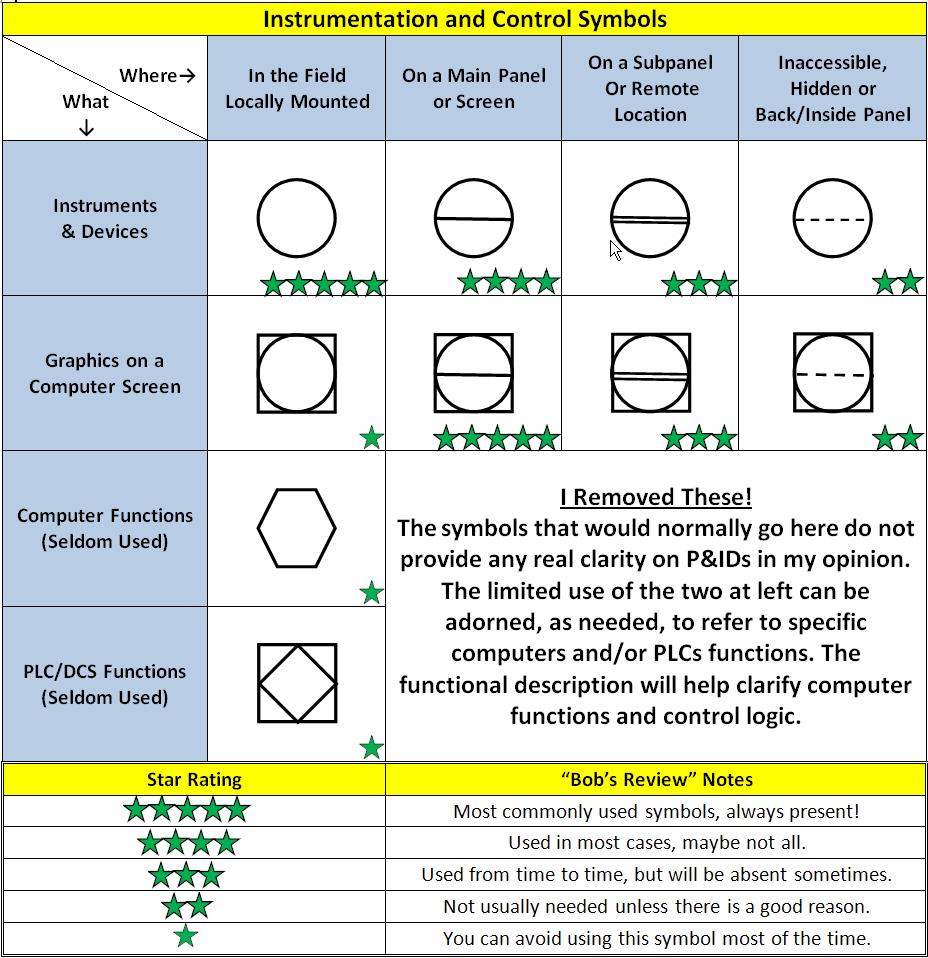
The main symbols used for Instrumentation and Control (I&C) are shown in the table above. When you spot one of these on a P&ID, you will be able to glean three things from it, including:
- What is that device?
- Where is it located?
- Why is it there?
The ‘what’ and ‘where’ aspects can be determined from the symbol shape. The ‘why’ part comes from text placed inside the symbol that is made up of two parts that form the « tag number ». This includes:
- An abbreviation for what the device is (based on ISA S5.1), combined with a
- Loop number based on your company’s preferred numbering system
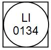
Before I dig into this topic more heavily, it’s worth providing a couple simple tag number examples as a lead-in. Pressure indicators have the abbreviation PI and temperature indicators use the abbreviation TI. It follows logically that flow and level indicators use the abbreviations FI and LI, respectively. Since most plants can have many instruments of the same type, a unique number is applied so that each one can be individually identified. This number is often referred to as the « loop number ». Thus, the device abbreviation + loop number become the unique « tag number ». While the device abbreviations are largely based on accepted standards (ISA S5.1), the loop numbering system is company specific. My group happens to use a four digit numbering system. In this case, typical tag numbers for pressure and temperature indicators in our plants will be PI0134 and TI4348, respectively. You could even reuse the loop number « 0134 » to define other types of devices, such as a level indicator, LI0134 or flow indicator, FI0134. The same holds true for loop number « 4348 »; it may be used for PI4348, LI4348 and HS4348 (where HS stands for Hand Switch). The key point is that the abbreviation + loop number must be unique for each device otherwise, it cannot be uniquely identified. You can get creative and apply special prefixes (or suffix) numbers to the tag number when you want to reuse the same tag (like in cases where you have redundant devices but you don’t want them to have different loop numbers). I will get into those when we look at the example P&IDs. But that is detail stuff.
What is that control symbol?
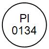
Refer to the first row in the table above. A circle symbol is quite simply any physical instrument or device in the field or on a panel. It doesn’t matter if it is a level transmitter, a flow meter, a pressure gauge or some other type of indicator. If it is a physical device that measures or displays something, it will be illustrated by the use of a circle on a P&ID. Notice also how I placed the tag number PI0134 inside the symbol. The common practice is to place the device function abbreviation on the top line, with the loop number at the bottom. When the device is ordered and a stamped tag is requested, it should match the tag number placed inside the symbol on the P&ID. Aside: Sometimes, you will hear folks refer to the symbols as instrument « bubbles ». This is just jargon that is commonly used. When you hear it, they are simply referring categorically to the symbol shapes I am talking about in this part. Just act like you’ve been calling them bubbles for years and show now sign of confusion!
Move down to the symbols on the second row of the table – the ones that show a circle inside of a square. These are used to represent a graphic on a computer screen or control panel that you can see and possibly interface with via touch panel or a computer mouse. It might be used to show the level in a tank (as the tab number in the bubble shown here suggests) or represent a hand switch that you can click on with the mouse to start a pump (or a million other things!). The point is if you can see it on a control screen, it will be represented as a circle inside a square on P&IDs. Don’t ask me who decided this, it wasn’t me! The last two rows are for symbols that let the reader know a computer is used to do some sort of complex processing. In the case of the hexagon, it means a « computer » is used. That’s a pretty vague description don’t you think? I mean, is your plant a « PC or a Mac »? I don’t want to get into that debate (my wife uses a Mac, otherwise I would) but my point is that some of these symbols begin to show their quaint age.
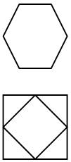
In the case of a square with a diamond in it, that means a programmable logic controller (PLC) is used. Ah yes, the venerable PLC – still hanging tough after all these years. Even if you are not familiar with control computers or PLCs, don’t sweat it. Just know that these symbols really represent software instructions that engineers write to define the automated behavior of the plant. For example, code that tells a pump to automatically stop when the tank it is pumping from runs low. That would be a so-called low level interlock type function that would exist as instructions inside a PLC. In this instance, a level element provides the input and the computer runs a set of instructions that say ‘stop the pump’ if tank level is low. These symbols are often left off of P&IDs because they really don’t provide any usable information that you could get out of just looking at the symbol. For example, in the simple example that I just provided, how could you describe the low level interlock using a symbol that looks like a square with a diamond in it? You couldn’t! You would need to supplement the P&ID with a written description of what the plant is supposed to do with all of the input it receives. So the symbols would just take up space and clutter the drawing for no good reason other than perhaps provide some pointer via a tag number to coded instructions. But the P&IDs serve the process, not the programmer so we can’t have that!
Symbology Star Power!

This brings me to the arbitrary star rating I gave all of the symbols in the table (see « Bob’s Review » key at bottom of table). Folks, this isn’t published by the ISA (as if I had to qualify this…) but we’ve been together long enough for you to know that this is how I roll. It’s my way of explaining the frequency and importance of these symbols in most cases. Here goes. For each symbol, I rate it based on how often it typically shows up on drawings that I have worked on over the years. Every plant is different but there is a general theme here. I view symbols with only one star as pretty much useless because the abstract concept they are trying to illustrate simply can’t be done effectively with just symbology. Two star symbols have value but may not show up very often or at all in many cases, depending on the type of plant and its design. Anything at or above three stars is a celebrity in our P&ID feature presentations. We’re talking Arnold Schwarzenegger, whereas the one star symbol is akin to the nondescript ensign killed off in the first five minutes of a Star Trek episode. So what about those quizzical computer symbols that I poke fun of? Well, you can still use them if you want but they need heavy support from a document that describes all of the functional requirements of a plant and that is typically called a Functional [Control] Description. Maybe in a future series (if you’re good), we will cover functional control aspects. Oh Goody! I can almost sense your joy at the thought! Hey, pay attention and no smart remarks. We still have work to do here!
Where is the device located?
If you glance back at the table, you will see that there are four columns that provide the ‘Where’ part of a symbol. Now, as we discussed in Part 2 of this series, P&IDs generally aren’t good at showing you where something is located in the field. We aren’t talking about that kind of ‘where’. In this case, we are using where as a relative reference. Relative location is indicated via the presence of a centered, horizontal line (or lack thereof), a dual centered horizontal line, or a dashed centered horizontal line placed inside the symbol;
- Single horizontal line – located on a main control panel near the control room or some computer screen in the main control room,
- No horizontal line – located somewhere in the field, probably close to the general area shown on the P&ID,
- Double horizontal line – on some secondary (satellite) local panel in the field.
- Single dashed horizontal line – inaccessible or not generally located where it can be easily accessed or viewed. May also be used for hidden or password protected areas of a control system.
Notice in the above items, no specific location information is provided, only that the device or graphic is associated with a relative, general location. In many cases, it’s not hard to figure out where something is just from where the symbol is at on the drawing. But there are limits to what the symbol can convey.
More on the Dashes
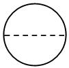
I have found that the dashed line symbols can cause confusion so I want to speak on those a bit more. When you see a symbol such as the one shown at left, that simply means that you can’t normally see it or work with that device it in the field. It might be installed behind or inside of a panel so that it is normally not in view (inaccessible to the operator). So in the symbols shown here, a circle with a dashed line in the middle means it is an instrument or device that you can’t normally see or get to. If you are an operator, it is probably something you do not need to get to but it might still be vitally important to the plant control system, so we show it this way on a P&ID. In a similar fashion, a graphic display symbol with a dashed line in the middle simply means that this portion of the control system is password protected or hidden from normal view on a screen or operating panel so you can’t get to it unless you know the secret access code. It’s not that people are keeping secrets from you (or maybe they are…hmmmm); it’s just that it might contain important settings that nobody should ever need to mess with.
Why is that device here?
You’ve come a long way towards understanding control symbology. You can now identify what a control symbol represents and its relative location in the plant. But you still don’t know why it’s there. It’s not helpful to know how to identify a control symbol type if you cannot explain what purpose it serves in the plant. That is the point of the textual abbreviations placed inside the symbols. We touched on this a bit above so now lets cover the essence of what you need to know – and keep in mind, come of this is the way I like to do things, which doesn’t necessarily mean it is the best or only way. Refer to the figure below entitled « Instrument Symbol Tag Identification ». A control symbol will typically contain two lines inside it, as follows:
- Upper Line – an abbreviation for the functionality it provides (based on the ISA 5.1 standard), and
- Lower Line – a loop number that corresponds to the equipment or area it is associated with (or based on your company’s preferred standard).
The upper line text abbreviation, along with the lower line tag number makes up the unique symbol identification tag. It is important that each symbol have a unique tag so that it can be individually identified. In this example, the symbol would be referred to as PDIT1703 in a process document or operating procedure. There may be a bunch of other symbols with 1703 in them, but they must have a different text abbreviation before the 1703 or you won’t be able to uniquely identify it. Part 4 of this series will talk more about typical device tagging protocols but for now; consider this your « Introduction to Tagging 101 ».
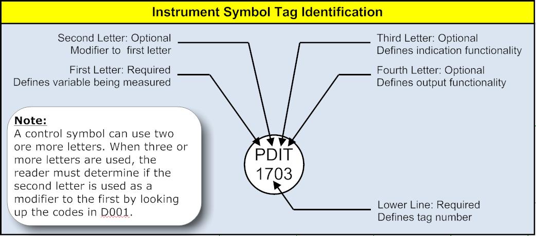
The letters on the first line are in accordance with ISA standard 5.1, as described in the upper left corner of lead sheet D001. Each letter provides unique information. We can use the table in D001 to determine that this symbol represents:
- « P » – First Letter stands for « Pressure »
- « D » – Second letter is a modifier for the first and stands for « Differential »
- « I » – Third letter stands for « Indicating »
- « T » – Fourth letter stands for « Transmitter »
- 1703 is the loop number (the Electrical Engineering eggheads need loop numbers too)
I like to base loop numbers off the associated major equipment. That’s just me, and I think it makes good sense. But if your company uses a different technique, roll with it. Now is not the time to be a renegade creator of new tagging systems. Fight your battles but win your wars! So in this case, we have a pressure differential indicating transmitter installed on equipment 1703. You might see such a device across a strainer inlet and outlet to let you know what the pressure drop is across it so that you can clean it when it gets high.
Common Instrument Abbreviations
There are a number of instrument letter combinations that you are likely to come across a lot. A few of these are listed in the figure titled « Common Primary Device Symbols ». These examples will help you get some practice understanding the abbreviations used for control symbols. You can compare the examples to the table on D001 to get the hang of it. These examples all represent field-mounted devices. We know that because they are all simple circle symbols with no horizontal lines. I told you this was pretty straight forward!
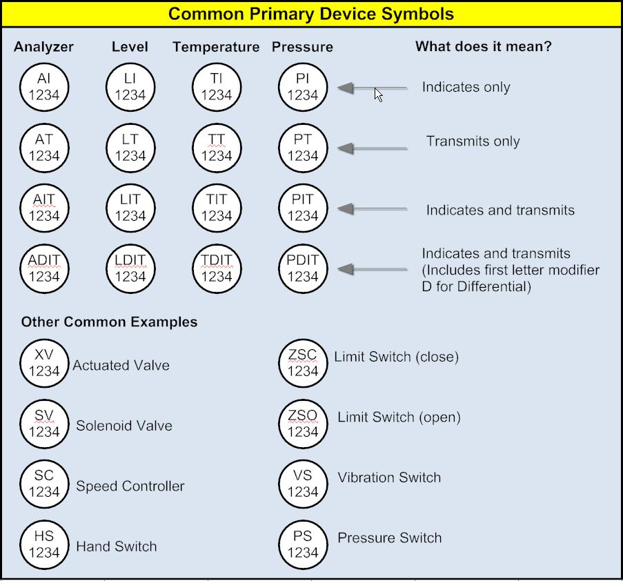
The hardest part in deciphering the abbreviations inside control symbols is figuring out what the letters designate when there are three or more letters used. Here are a couple rules of thumb:
- In the case of abbreviations with four letters, the second letter is a modifier to the first.
- When only three letters are used, the second letter probably is not a modifier.
As with any « rule of thumb », you mileage may vary, so if in doubt, look it up using the table on D001 (or your own company lead sheets).
Symbol Attributes
Depending on the symbol purpose, various other attributes may be placed near control symbols in « supporting role ». The section called « Instrument Abbreviations » on lead sheet D001 defines some of the more common ones you might run into. These are simply helpful bits that provide further clarification for the situation at hand. In many cases, it is helpful to know « at a glance » that a valve is FC (Fail Closed) or that DI is a (Digital Input). Refer to this table when you encounter abbreviations used around control symbols.
Instrument Input-Output (I/O)
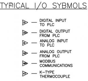
Despite major advances in computer technology and communications protocols, many instruments still transmit their signals using a trusty analog signal (via a 4-20ma, 24V). For switched devices, the input is typically a switch that simply provides a voltage input. While it is not a common practice to show the type of signal a particular device sends to and/or receives from the control system (collectively referred to as the I/O), in my company I like to employ simple triangular symbols along the interconnecting lines to help illustrate the I/O flow (if you will) on a P&ID. This is illustrated using the symbols shown in the figure below. The important point to remember when you see these symbols is that the I/O flow is always from the control computer’s perspective. Thus, all outputs (DO, AO) come out of a output module and go to some field device. Conversely, all inputs (DI, AI) are signals from field devices that flow into some input module. Other types of I/O that may require specialized transducer cards or network protocols are sometimes used. For example, the KT signal is a common type of signal that a thermocouple employs. You may have also heard of RTD temperature sensors. There are a myriad of transmission protocols used today and as process engineers, we don’t need to get caught up in that. But it is helpful to understand the flow of I/O in a plant and using these symbols is a cheap, easy way of showing that with no penalty on the complexity of the drawing! All of the I/O symbols invariably link to the software line type (described below), as this is used to illustrate software processing within a computer or PLC. You don’t know what is taking place just by looking at a line, but you can be sure that whatever it is, the Functional Control Description is the place to look to find out.
Line Symbols
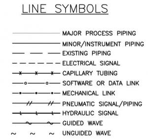
The key line types are highlighted in the figure at right. By far, the most common line type is the solid line, which is used to represent a pipe. Although not shown, a process line with long dashes means the pipe is existing or is outside the battery limits (OSBL) of the plant. Other common line types that you should be able to identify are electrical signal (anywhere wires are employed), instrument air to control valves/devices (labeled as pneumatic signal) and software or data link which includes « virtual » communication such as what occurs inside a computer program or PLC ladder logic. The software can include anything that happens inside a computer, but you need a functional description to actually know what that is, as we discussed earlier in this brief. Just know that when you see a software line, it means computers are at work linking the devices in some meaningful way that relates to the system controls.
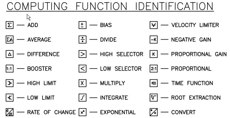
Computing Functions
These symbols describe the types of functions that run inside a computer program. A problem with applying these symbols is that they do not really provide solid insights into how the plant is controlled in complex instances. For this reason, most P&IDs will make limited use of computing function symbols. You can safely ignore these and not miss out on much because the functional control description is really intended to describe control details that these symbols try to illustrate.
Valve Symbols
The figures below show the key symbols for the various types of manually-operated valves and actuator details for automated valves. Note the attributed stems on the actuators to indicate fail state. This is a good example of using attributes to provide key information that is valuable to operations.
Connection Types
Regarding connections, the symbology shown in the figure below is standard. One point I will make is that in plastic piping systems (PVC, CPVC and ABS), everything is generally glued using a connection type called « socket weld ». However, socket weld can also be applied to metallic piping systems where a welded connection is employed using socketed (versus butt weld) fittings. There is no specific designation between glued or welded socket connections. Nor is there a symbol for threaded connections.
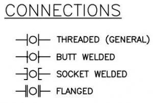
When you start getting into what type of connection should be used in a particular pipe, this is not really something that is based on personal preference or simply what you might have on hand in the maintenance trailer. This is something that is based on things like the line service (what’s in the line), conditions (temperature, pressure), and other factors (like supporting requirements). This kind of stuff is defined in a Material and Line Specification Standard. We won’t cover that in detail here but you know what? I just got an idea! This is great topic for a future series. The fun never ends does it?
What about pipe fittings?
In case you are wondering (and I know you were), P&IDs generally do not show pipe fittings (elbows, tees, unions, o-lets, etc.). Nor will they include all the various flanged connections
that might actually exist in the plant. These are details that show up on piping plans/sections, isometrics and fabrication drawings. So, unless it is important to the process design for some reason, fittings and extraneous flanged connection are generally not shown. If you need to get a fitting take-off, look elsewhere!
Transducer Functions
This is an area that defines signal conversion. Only electrical engineers get excited about this stuff, and you really don’t need to focus too much on this. In fact, I almost skipped it but I just know that if I did someone would ask, so let’s get this out of the way because this electrical stuff is starting to get a tad boring… A transducer is something that takes a signal in one form and converts in into another form so that it can be used by a downstream device. For example, a control valve may need air to actuate but receive an electrical signal to tell it to do that. Somehow, you have to get the electric signal converted into an equivalent air signal so the valve can move. Hello signal transducer.

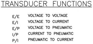
In this particular example, an I/P (current to pneumatic) transducer is necessary so that the valve can be positioned to any desired opening point with just an electrical signal. This is the most common transducer function used in many plants; the others listed are comparatively rare. So, understand what I/P means when you see it and don’t worry too much about the rest of them for now. When you graduate to Master Ninja P&ID interpreter, then we will focus on these details.
Primary Flow Elements
These symbols are nothing more than graphic illustrations that complement the control bubbles to help readers of the drawing more easily identify the type of flow element being employed. The most common types are shown in this table on D001. These symbols are not really critical towards an understanding of the instrumentation or controls. Level elements don’t have an equivalent. Nor do other common instrument types.
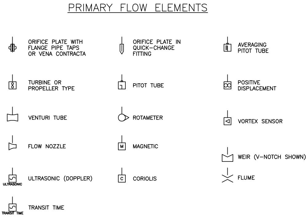
Breaktime!
OK, so now you have a solid feel for what P&IDs are, the purposes they serve, their limitations and supporting document requirements and now – a pretty solid handle on the symbology used. Despite all the ground we covered in this part, we haven’t really had a chance to go through a few examples. Everyone knows that when it comes to learning new information, application it is key. The old adage « use it or lose it » applies. I still aim to get to some examples but for now, just take a well deserved break and let this stuff sink it. Besides, I’m sure they need to go buy a couple more hard drives for Parts 4 and 5.
Part 4 – Codes, Tags and Labels
So you are back for more in Part 4? After all we went through in Part 3, those still standing probably deserve a medal or something. That said, unlike Part 3 where we really covered a lot of detailed « nuts-and-bolts », this part will be a comparative piece of cake. Kind of like the last day of school where you know you still need to go and it might even be kind of fun, but you don’t have to do any real work and the stuff you do take home will be memories not homework. That’s the frame of mind you need to have for Part 4, ok? But before you take this as a cue to start shooting spitballs at your host, sit up straight because this part is vital to your understanding and development of clean, clear, odor-free P&IDs. Since this series is kind of long (hey, who snorted!?), let’s get the requisite recap out of the way for those who missed the previous parts and need to circle back:
- Part 1 talked about why the interpretation of P&IDs is important to everyone involved in the planning, design, and construction through operation of a process plant.
- Part 2 described the various functions P&IDs serve and highlighted the kinds of information they convey, along with the support documents that are commonly associated with them. We also talked about some of their weaknesses.
- Part 3 covered the nitty-gritty aspects of instrumentation and control symbology. Along with that, we dissected tag abbreviations and how loop numbers uniquely identify devices. Since we were on a roll, we closed out this part with all the ancillary I/O symbols, line types, piping connections and other various sundry items peripheral to the main theme.
Up till now, we have spent a great deal of our time focusing on the first lead sheet, D001 – Instrumentation and Valves, provided along with other drawings in the supporting file download to this series. In this Part 4, we will turn our attention to the remaining lead sheet, D002 – Codes, Tags, and Labels. As I have mentioned previously, D002 is an example lead sheet typical of the ones I have

used in the past. It may look different from the ones your company uses and that’s OK. It’s not as important how a company prefers to do labeling on a P&ID, only that they do it clearly, consistently and based on a robust system that is amenable to future change and additions. An extensible tagging system if you will. That’s a concept that may be a bit unfamiliar to some so I will discuss that as a sort of prerequisite. Hang in there, I see the finish line…just around the corner!
P&IDs Are Really Databases, Wait..what?

While P&IDs are representations of the process to the casual observer, their underlying structure more closely resembles a relational database. In fact, for those of you familiar with today’s common computer aided drafting packages, you may realize that a CAD drawing is really a database of objects assembled in a structured manner. Even if you reuse the same object over and over in a drawing, the CAD system keeps track of it with a unique identifier. This is very similar to a process plant in that, well for starters, we apply tags to keep track of equipment, piping, valves, devices, etc.–things that we reuse over and over again in any given process design. So I am here to tell you folks, when you design a process and develop the P&IDs in CAD, you are really assembling a database along the way. This isn’t lunacy with half a bowtie. I’m serious and I would urge you to get familiar with relational database design, if only from an academic standpoint. Like object-oriented programming, these abstract concepts are extremely valuable towards implementation in our line of work. Some examples? Ok, behold my exhibits–like a database, a process plant illustrated using CAD on a set of P&IDs:
- Contains collections of similar objects with unique tags so that even identical objects (valves, pumps, instruments, etc.) can be uniquely identified.
- Is assembled in a structured manner that lends itself to additions, deletions, changes, etc. with a granularity as coarse as whole unit areas, down to a single valve on a pipe anywhere in the plant.
- Contains lots of metadata in the tagging systems that can inherently provide (or link to) much more detail such as specifications, materials of construction, data sheets, etc.
There’s more than just the above but I will rest my case. I hope you agree that while the tags and labels themselves are self-evident, the real power is in the underlying tagging system used. And so you’re still thinking, « why must a tagging system be so robust and extensible? I mean, come on Bob, aren’t you making a mountain out of mole hill? » Well, glad you asked; the answer is quite simply because most plants change over their useful life. Change comes from a lot of different angles:
- Operational Tweaks–improvements often come from the operations folks. In my experience, some of the best improvements to a plant don’t come from the egghead engineers sitting in their cubicles, but from the folks in the plant dealing with the machine each and every day. It is in their interest to make it work better, safer and cheaper.
- Capacity/Production Changes–often, a particular unit operation needs to be expanded to meet new production requirements or changes in feedstock or product requirements that shift the process design needs. I’ve seen instances where complete new trains have to be added to a system.
- PSM Audit Review–Process Safety Management requires that process documentation be kept up to date and routine plant audits and Process Hazard Review may reveal changes that should be implemented to a plant that is already in operation. The P&IDs are the reference upon which such reviews are based and must always be in a current « As-Built » state.
The key take-away from the list above is that the P&IDs serve initially as the process definition upon which the plant is designed. But then they serve operations long after the plant is built. This is why earlier in this series I espoused the need for engineers to be routinely, actively engaged in ongoing operations. Not only will you learn a lot about the plant that you yourself may have helped build, the feedback you receive will be invaluable to maintaining a safe operation. Plus, you can implement the lessons learned on future projects. Now that I’ve driven home the importance of a structured tagging system, let’s turn attention to the meat of this Part 4–the actual tagging of equipment and devices.
Equipment Tags
Lots of companies use what appears initially to be an intuitive, simple system to tag equipment. It later reveals itself not to be very intuitive or robust. Let’s pause for fictitious example (that bears no resemblance to my past, really). GitRDun Process, Inc. has decided to build a new plant to produce Trimethylkabif, a precursor to a drug that yields quick weight loss, improved memory and muscle tone while eliminating irritable bowl, gastric reflux and attention deficit. The process folks start out tagging equipment as follows:
- Pumps are simply tagged P-1, P-2, P-3 (makes sense right?)
- Agitators are tagged AG-1, AG-2, AG-3, etc. Dude – this is so simple!
- And of course tanks and vessels are tagged TK-1, TK-2, TK-3 (or V-1, V-2, V-3). Could do this in my sleep…
And so on…Life is good. Later on, though less common equipment starts getting added, and this starts to stress the « intuitive » nature of the system. For example, a centrifuge is initially tagged C-1 but now they need to add a conveyor but C is taken so they decide to call the conveyor CO-1. Now they think, well, we will just revise the centrifuge tag to CE-1. Crisis avoided…But wait, later they need to add a chemical feed package and want to tag that CF-1. OK, that’s cool but then a bunch of cross flow filter modules is added they decide to « steal » the CF label for those and change the chemical feed to CE, no wait…can’t do that, CE is taken by the centrifuge. So they bite the proverbial bullet and call the chemical feed skid CS-1 where S is « intuitive » for supply. Right? Try again quiz kid. Nobody is going to see that as intuitive. And then one day, it hits GitRDun’s process engineers that their initially conceived so-called intuitive tagging system is a heap of broken confusion and nobody knows their CE’s from their CO’s. Cue the Jackson 5 song A B C, simple as 1 2 3!
A Better Tag Numbering System
To avert the problems inherent in the above example, many process industries utilize a numeric-only system for tagging equipment. This helps simplify the logical categorization of equipment during the process design phase. Moreover, a structured tag system is more intuitive for the development of design documentation, operating procedures and training, and general documentation upkeep/maintenance. With that in mind (and considering the points presented earlier in this Part), the following method is but one example of how to tag process equipment using an extensible system.
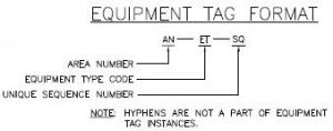
Area Number, AN Most sizable process plants are comprised of multiple areas. An area is a physical, geographical, or logical grouping determined by the site. It may contain process cells, units, equipment modules, and control modules (more details can be found at isa.org). To facilitate a hierarchical organization of equipment, equipment tags should then incorporate area designation.
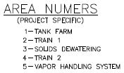
A small or simple project may have only one area. Conversely, larger more complex projects may have multiple areas. The assignment of areas is at the discretion of the process engineer and can be subjective. The only general rule that I like to employ is that common equipment that serves multiple areas, e.g., utility and infrastructure system be placed into a « Common Resources » area rather than be made a part of any other process area. Once areas have been designated for a particular project type, engineers should strive to maintain common area designations on future, similar projects. For example, the areas shown in the figure above may be defined on the lead sheet for a fictitious project.
Equipment Types, ET
Equipment can be identified based on its type using a numeric system such as the simple one shown below. In cases where equipment has multiple functions, user discretion is advised in selecting the most suitable type code.
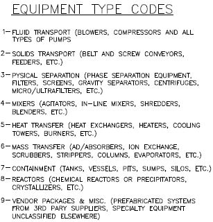
Sequence Number, SQ
This is the consecutive numbering of like equipment in a particular area. The sequence begins with 01. All equipment is to a have its own sequence number. The use of alphabetic or other tag suffixes is to be avoided.
Example Equipment Tags
Using the system outlined above, a four-digit system emerges that may not be instantly recognizable in terms of what the specific equipment is (or where), but it will eventually become very familiar to those who are intimate with the plant. A few examples using the area numbers defined above are provided below:
- 1101 – The first pump in the tank farm area.
- 1701 – The first tank in the tank farm area.
- 1405 – The fifth mixer in the tank farm area.
- 2901 – A vendor package in the Train 1 area.
The equipment tag number should be prominently displayed near the symbol used for the equipment. For example, the tag number for a centrifuge might appear as follows on a P&ID.
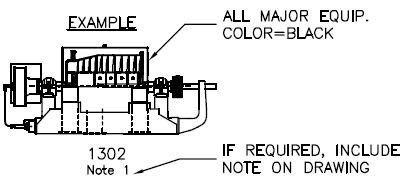
Lastly, all major equipment should be named and provided general specifications in a label placed along the drawing border. A couple examples for a pump and tank follow.
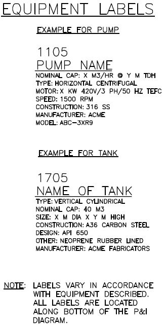
It is up to your company to decide on the final formatting, location (some companies like to put certain equipment labels near the top of the border), and which particular specifications should be included along with each major equipment label. The system presented here is fairly simple and broadly applicable. Irrespective of these details, I highly recommend that every piece of major equipment receive a label with a similar level of detail.
Instrument Loop Numbers
A benefit of using four digit equipment numbering system such as the one presented above is that the tags lend themselves toward application in defining associated instrument loops. This makes grouping equipment and associated instrumentation devices more logical. Think back to our friends at GitRDun Process, Inc. Their tagging system consisted of tags like P-1, AG-1, CE-2, etc. These tags are not amenable for use in defining instrument loops. However, a four digit system does neatly tuck into instrument bubbles and when you think about it, most instruments and devices serve or are primarily associated with a piece of equipment. And even when that is not the case, they can readily borrow from the equipment type code « 9 » in cases where, for instance, a pressure gauge on an air header serving the entire area must be defined. Considering the above points, the following instrument and device tagging system is but one effective way to tag instruments and devices:
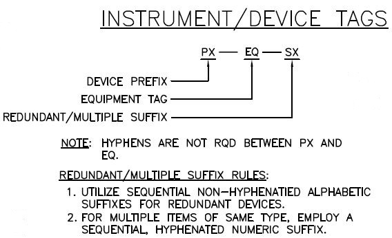
Where;
- PX – device type prefix (as per ISA 5.1)
- EQ – the associated equipment tag (as defined above)
- SX – duplicate or redundant device suffix (see details below)
Duplicate Suffix, SX Rules
A suffix is provided to accommodate instances were many devices of the same type are associated with a given piece of equipment. For example, a vessel may have many lines connected to it, each having its own actuated valve. To resolve these instances so that each device has its own unique loop number, there are two suffix tag methods that can be employed,
- If a piece of equipment has redundant devices associated with it, an alphabetic suffix may be appended to the loop number, e.g., FV1101A, FV1101B, FV1101C, etc. (Note: Redundant means serving the same purpose as another device in a backup fashion.)
- If a piece of equipment has multiple items of the same type, each of which with different functions (not redundant) then a numeric system should be employed, e.g., FV1101-1, FV1101-2, etc.
Example Loop Tags
Based on the above discussion, some example loop tags are provided below. If needed, the reader can visit a more though discussion in Part 3 regarding instrument abbreviations. (Note: In the examples provided, I use the example Area Numbers presented as examples above.)
- PI1101 – A pressure indicator on the discharge of the first pump in the tank farm area.
- LT1701 – A level transmitter on the first tank in the tank farm area.
- IT1405 – A current transmitter (for the motor) on the fifth agitator in the tank farm area.
- AE1701A – One of at least two redundant analyzers on the first tank in the tank farm. Hence, one would expect to see AE1701B, AE1701C… as indicated.
- XV1701-1 – An actuated valve on the first tank in the tank farm area. The suffix -1 implies there are other valves associated with tank 1701 but in an alternate service (i.e., not redundant). For example, XV1701-1 may be on the inlet to the tank, while XV1701-2 may be on the outlet.
Line Numbers
Similar to equipment and instrumentation, every pipe on a P&ID requires a unique tag number so that it can be uniquely identified during design, or referenced in operating procedures. Since most lines are also affiliated with a major piece of equipment to which they connect, I like to employ a numbering system similar to that used for instrument loops whereby the equipment tag is integrated into the line tag in the following manner (Note: D002 provides an alternate method that employs drawing number instead of equipment number but I generally prefer the method given below.)
X »–SVC–ET:SQ–LS
Where;
- X » – the nominal size of the pipe
- SVC – the service code for the material that normally flows in the line (see examples below for list)
- ET:SVC – a unique line tag that includes two parts, the equipment tag from which the line originates followed by a unique sequential number
- LS -line specification for the pipe, including class and material type, valves etc.
Service Codes, SVC
Service codes are abbreviations for the fluid the line primarily handles.
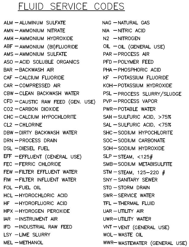
Since some lines can serve many different process fluids, the fluid used to specify the materials for the line should go here. The list should be available on a lead sheet in a manner similar to that provided in the example above.
Line Specifications, LS
Line specifications cover all the details related to the piping system used to handle the fluid for the line. This should include all details regarding material of construction, valves and trim, gaskets, fittings, T/P limits, and much more. This is beyond the scope of this series but is such a critical component of plant design that I might expand on this in a future post.
Hand Valves
Hand valves require a consistent and clear tagging system for reference in operating procedures. There are a number of techniques that can be used, but one that I generally prefer is as follows.
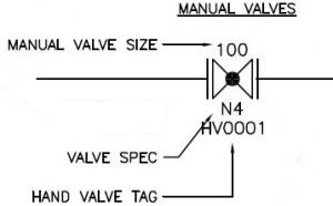
In the example provided at left, one can discern valve size, spec and tag number. This might be more information than you want to include on some P&IDs. In cases where you just want to show the valve tag and allow the spec and size to be derived implicitly from the line tag, the following method is one option:
« V » – D# – SQ
Where;
- HV or V – A literal and required part of all hand valve tags
- D# – last two digits of P&ID drawing number
- SQ – Sequence Number (01 to 99)
- V0001 – The first hand valve on P&ID D100
- V1205 – The fifth hand valve on P&ID D102
Example Hand Valve Tags
- V0001 – The first hand valve on P&ID D100
- V1205 – The fifth hand valve on P&ID D102
Wrap-Up
Further to the content in this part, D002 includes a few more examples of common tags and codes applied in P&IDs, such as insulation, interconnecting arrows, etc. These are important parts but are pretty self-evident. Aside from that, most companies have very specific ways and means on these items so I won’t cover them in depth here. Well, I started this out by saying it was going to be fun and simple and I hope you leave this series feeling like I made some solid points that will be of value to you going forward. In a follow-up to this series, I will put together a complementary video where I take a few typical P&IDs (like the ones I’ve attached here) and discuss all of these aspects in what I hope to be a much more engaging manner. You will then be able to get a much better feel for seeing and hearing this information. Now venture forth with your new knowledge and apply it for good. Stay safe and have fun.
Part 5 – Series Videos
Grab some popcorn and turn the lights down, it’s beer-thirty and time for a break. We’ve talked enough about P&IDs, and now it’s time to infuse the (sometimes) dry material with a bit – dare I say – excitement? While I’ve had fun with this series and even poked fun at myself for being a little nerdy (which I’m not), truth is, reading about process drawings can get a bit stale. So, as I promised at the outset of the series, I’ve put together a few videos to help cement and highlight aspects that are hard to do by the written word. In so doing, I even manage to slip in some bonus features that I didn’t talk about in the written parts of this series! First, an introductory video:
Introduction to Interpreting Piping and Instrumentation Diagrams
Next up, a three-part video series focusing mostly on instrumentation bubbles:
https://www.youtube.com/watch?v=dqInt1AoDV8
https://www.youtube.com/watch?v=XjUt0nshGFE
https://www.youtube.com/watch?v=UVriaH5x1w0
After the above, I complete the remaining aspects on the first lead sheet with the following two videos:
https://www.youtube.com/watch?v=_FQybMJPyeE
https://www.youtube.com/watch?v=ZvgTviVsH-w
Or you can head on over to my page at YouTube to check them out! Hint: Be sure to start with the introductory video and work your way down the series. Since YouTube limits videos to 15 min each, I had to break some of the videos up into parts. These videos don’t cover the second lead and other items that I want to cover. I plan to cover those in an appended post. Folks, thanks for hanging tough with me on this extended journey. I put you through it because it’s important stuff and, in all honesty, I still love talking about it. Aristotle said « Pleasure in the job puts perfection in the work. » – Bob
Valve Symbols in P&ID – Ball Valve, Relief Valve and more
In this article, you are going to learn about different types of valve symbols used in P&ID. Many types of valves are used in process piping and each has a different symbol. This makes the valve one of the tricky parts of reading P&ID. But with practice, you can easily remember these symbols and can read P&ID effectively.
There are two types of valve symbols — first, generic symbols, and second, a symbol with a modifier. Generic symbols will tell you that there is a valve in the line, but it will not tell you about the types of the valve. Whereas the valve symbol with modifier will tell you the exact type of valve that is used in the pipeline.
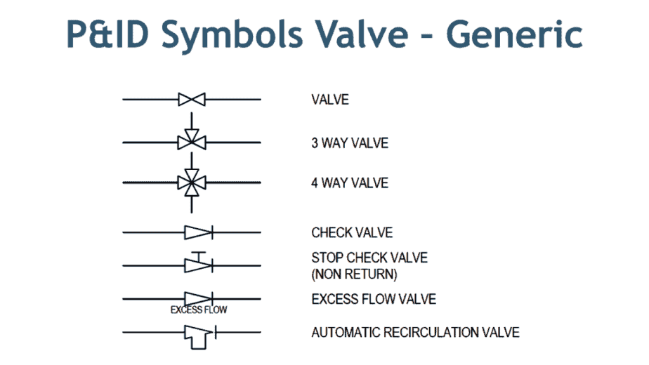
Here in the image above, you can see commonly used symbols for valves. These symbols are generic in nature — for example, the first symbol of a valve.
Now when you look at the symbol on drawing, it just gives you an indication that some kind of valve is used, but it will not provide you with information about the type of valve whether it is a gate, globe, or plug type valve. There are dedicated symbols for a gate, globe, plug, ball valves which I will explain to you in minutes.
Similarly, the next two symbols are for three-way and four-way valve. It can be a plug or ball valve. Subsequent two symbols are of a check valve and stop check valve. These check valves can be swing check or lift check valve.
The next symbol is the excess flow valve. You can see that it is the same as a check valve with the only difference is the written text, below the valve symbol. You have to be very careful while reading this type of symbol as it can easily overlook.
The last symbol is of automatic recirculation valve. This type of valve is used in the pump discharge line to ensure the pump will not suffer from low inlet pressure which leads to cavitation.
Watch this video which will explain to you all aspects covered in this article.
Relief Valve Symbols
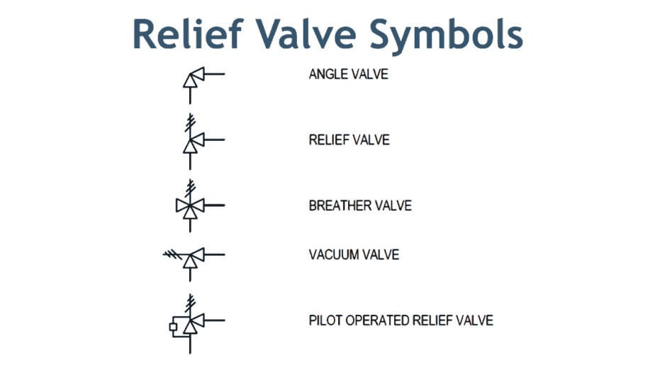
Here in the image above, the first symbol is of angle valve. In most cases, a globe valve is used as an angle valve. The next symbol is of relief valve that used to protect the piping system or equipment from overpressure.
Now the breather valve is used on the cone roof tank. This valve serves the function of the relief valve and vacuum valve. In the event of over-pressure, this valve release the pressure, and in case a vacuum is created in the tank, this valve allows air to enter the tank. Just like breathing air in and out.
The vacuum valve prevents damage to the equipment from negative pressure. Pilot operated relief valve are just working as a relief valve, but are used for large size piping. In this type, a small relief valve is used to operate the main relief valve. This arrangement is cost-effective in the large size relief operation.
Now I will explain to you the specific valve symbol that used in P&ID and isometric drawings.
If you want to learn about more than 18 types of valves in detail, you can buy my course, how to be an expert in piping valves.
Gate Valve Symbol
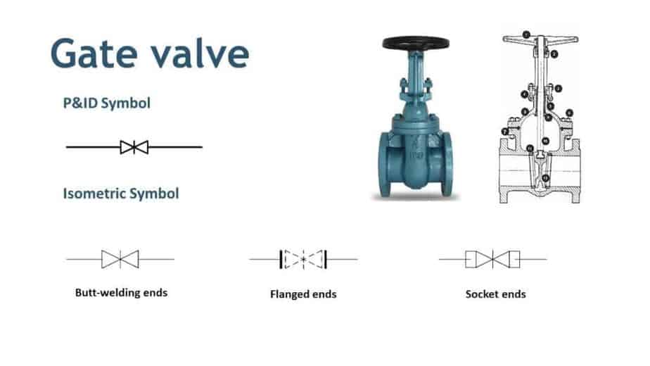
In the image above, you can see the gate valve. Now see the P&ID symbol for the gate valve. It is a modification of a generic valve symbol by inserting a vertical line between two triangles. Three symbols shown below are the gate valve symbols used in isometric drawings. The first is for butt-welding ends, second is for flanged end valve and the third one is for socket end connection.
Globe Valve Symbol
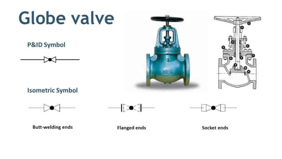
For a globe valve, a symbol is modified by adding a small dark circle between triangles. You can see that P&ID and isometric symbols are almost the same with the only change in end types.
Ball Valve Symbol
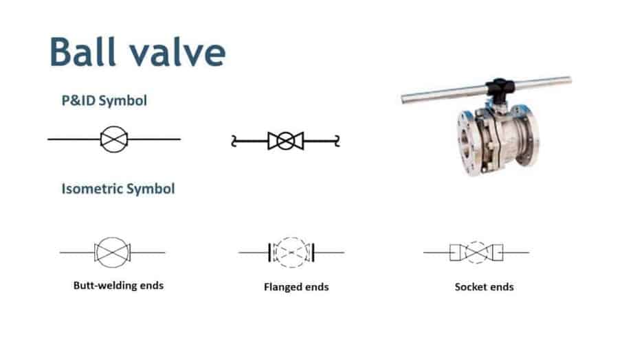
You can see that there are two P&ID symbols for a ball valve. The reason is that P&ID and isometric drawing symbols are changed from company to company. So if you switch the company, you should be aware of this. Similarly, you can see the ISO symbols for butt, flanged and socket ends ball valve.
Needle Valve Symbol
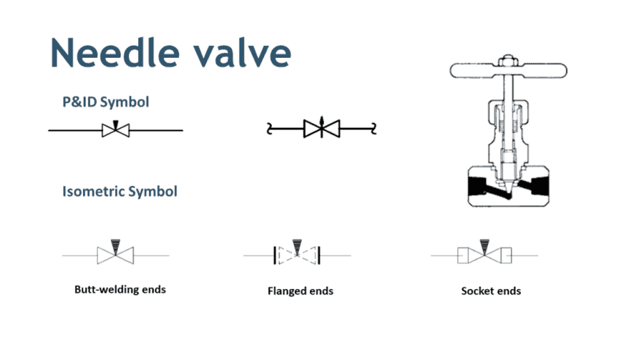
Same as a ball valve, a needle valve also has multiple P&ID symbols. If you can see that even these symbols are different but still you can easily interpret. If you are using second P&ID symbols, your isometric symbol will be changed accordingly.
Plug Valve Symbol
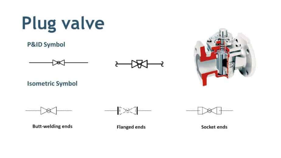
For the plug valve, the first symbol is a bit confusing with a globe valve. If you remember the symbol of a globe valve, it has a dark circle in between the triangle, whereas here only circle outline is there. So when you see this type of symbol, better to double check the drawing.
Butterfly Valve Symbol
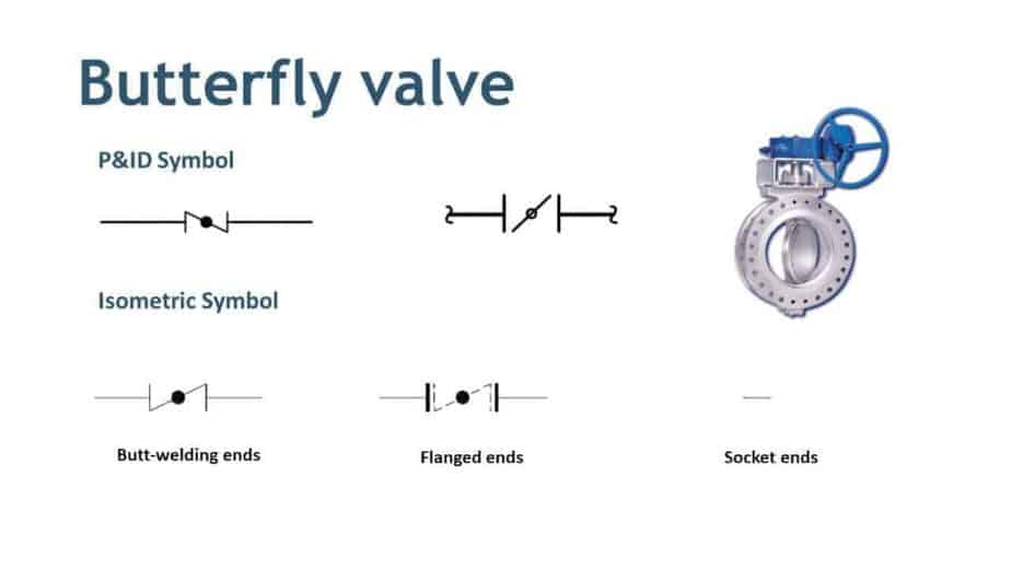
Butterfly valve symbol is the only symbol where a full triangle is not used. If you refer to the first symbol, it is similar to a globe valve but a triangle is not full. The alternative symbol is clearer in this case. For isometric symbols, you can see that there is no socket end butterfly valve.
Diaphragm Valve Symbol
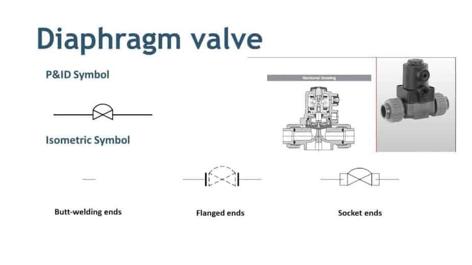
Here is the diaphragm valve. There is no butt-welded diaphragm valve available. Most diaphragm valves are flange type and they are used to handle process media with solid particles.
Special Valve Symbol
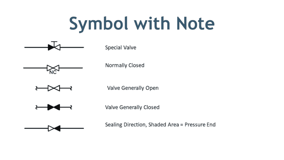
In the image above, you can see the symbols with a special note. The first symbol is a special valve. The word NC return below the second symbol is more important. It indicates that this valve remains closed during normal operation. Now the next two symbols are also used alternatively to show the valve position during normal operation.
The last symbol used to show the pressure end of the valve. The shaded are showing the pressure side of the valve.
This is all about P&ID and isometric symbols of Valves. If you want to learn about equipment symbol that uses in drawing check this article.
Different Types of Valves used in Piping – A Complete Guide of Pipe Valves
Different types of valves are used in piping. In this article, I have covered classifications of valves and functions of valves. Let’s start with Valve’s definition.
What is Valve?
Chances are there that you already know this. But there is no harm to refresh the memory.
A valve is a device that regulates, controls, or directs the flow of a fluid by opening, closing, or partially obstructing fluid flow. A sound bit complicated? Ok, let me further simplified this. A valve is a mechanical device that controls the flow and pressure of fluid within a system or process. So basically, it controls flow & pressure.
Types of Valves
In piping following types of valves are used depending on the requirements. The cost of Valve in the piping system is up to 20 to 30% of the overall piping cost. And the cost of a given type and size of the valve can vary 100%. It means that if you choose a ball valve over a butterfly valve for the same function. It can cost you more. So, the selection of valves is essential to the economics, as well as operation, of the process plants.
- Gate Valve
- Globe Valve
- Check Valve
- Plug valve
- Ball Valve
- Butterfly Valve
- Needle Valve
- Pinch Valve
- Pressure Relief Valve
Let learn about each of them.
Click on the link to learn about each of valve in more detail.
Gate valve
A gate valve is the most common type of valve in any process plant. It is a linear motion valve used to start or stop fluid flow. In service, these valves are either in a fully open or fully closed position. Gate valves are used in almost all fluid services such as air, fuel gas, feedwater, steam, lube oil, hydrocarbon, and all most any services. The gate valve provides a good shutoff.
Click on the image given below to learn about following types of Gate Valves.
- Solid Wedge Gate Valve
- Flexible Wedge Gate Valve
- Split wedge or Parallel disks Gate Valve
- OS & Y Gate Valve or Rising Stem Valve
- Non-rising Stem Gate Valve or Insider Screw Valve
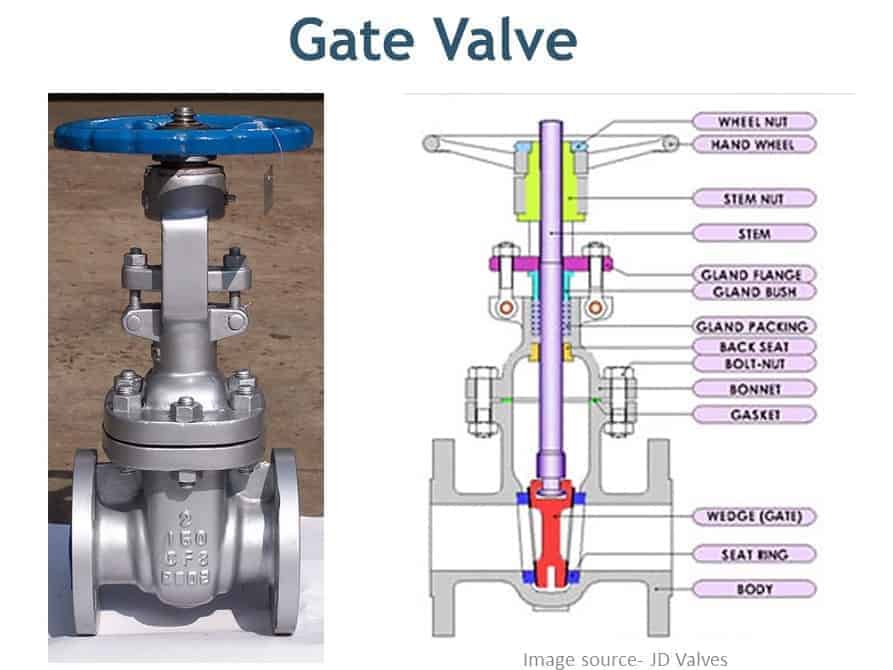
Globe Valve
Globe valve is used to stop, start, and regulate the fluid flow. Globe Valves are used in the systems where flow control is required and leak tightness is also necessary. Globe valve provides better shut off as compared to the gate valve and it is costlier than a gate valve.
Click on the image given below to learn about following types of Globe Valves.
- Z types
- Y types
- Angle Types
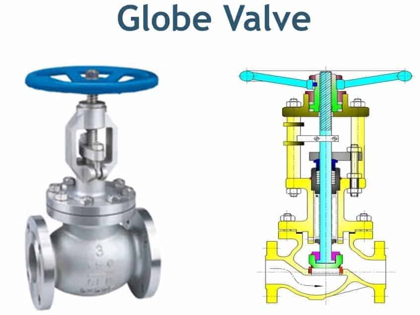
Check Valve
The check valve prevents backflow in the piping system. The pressure of the fluid passing through a pipeline opens the valve, while any reversal of flow will close the valve.
Click on the image given below to learn about following types of Check Valves.
- Swing Type
- Lift Type
- Dual Plate Type
- Stop Check Valve
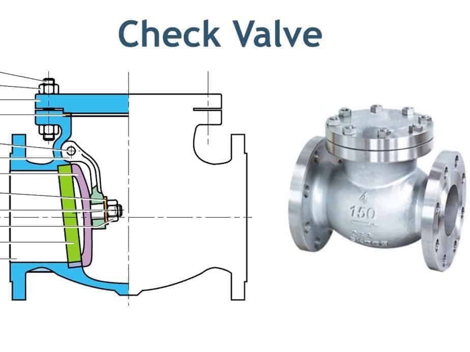
Plug valve
Plug valve is a Quarter-turn rotary motion Valve that uses a tapered or cylindrical plug to stop or start the flow. The disk is in plug shape, which has a passage to pass the flow. Plug valve used as on-off stop valves and capable of providing bubble-tight shutoff. Plug valve can be used in a vacuum to high-pressure & temperature applications
Click on the image given below to learn about following types of Plug Valves.
- Rectangular Port
- Round Port and
- Diamond Port
- Lubricated Plug Valve
- Non-lubricated Plug Valves
- Multi-Port Plug Valves
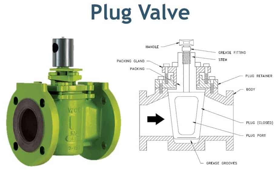
Ball Valve
A Ball valve is a quarter-turn rotary motion valve that uses a ball-shaped disk to stop or start the flow. Most ball valves are of the quick-acting type, which requires a 90° turn of the valve handle to operate the valve. The ball valve is Smaller and lighter than a gate valve of the same size and rating.
Click on the image given below to learn about following types of Ball Valves.
- 3 Way Ball Valve
- Floating Ball Valve
- Trunnion Mounted Ball Valve
- Top entry
- Side entry or split body
- Three-piece body
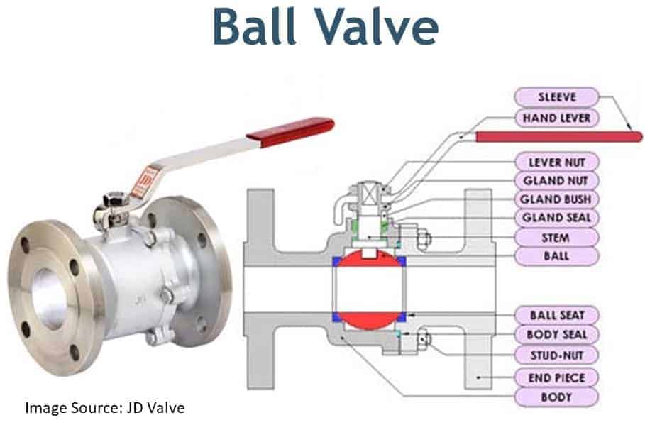
Butterfly Valve
A Butterfly valve is a quarter-turn rotary motion valve, that is used to stop, regulate, and start the flow. The butterfly valve has a short circular body. Butterfly Valve is suitable for large valve applications due to Compact, lightweight design that requires considerably less space, as compared to other valves.
Click on the image given below to learn about following types of Butterfly Valves.
- Flanged Ends
- Wafer Type Ends
- Lug Type Ends
- Butt Welded Types Ends
- Zero offset Butterfly Valve
- Double Offset Butterfly Valve
- Triple Offset Butterfly Valve
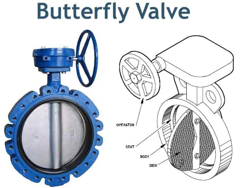
Needle Valve
Needle valves are similar to a globe valve in design with the biggest difference is the sharp needle-like disk. Needle valves are designed to give very accurate control of flow in small diameter piping systems. They get their name from their sharp-pointed conical disc and matching seat.
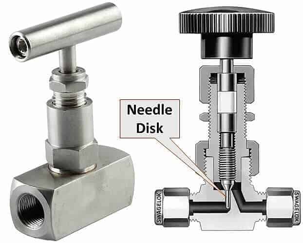
Pinch Valve
The pinch valve is also known as a clamp valve. It is a linear motion valve. Used to start, regulate, and stop fluid flow. It uses a rubber tube, also known as a pinch tube, and a pinch mechanism to control the fluid. Pinch Valve is ideally suited for the handling of slurries, liquids with large amounts of suspended solids, and systems that convey solid material pneumatically.
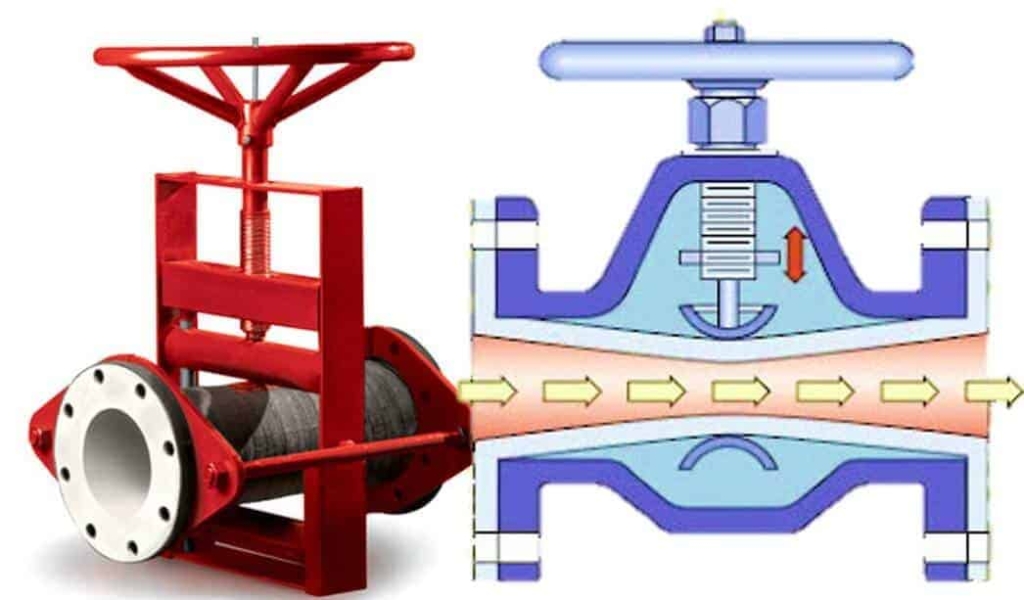
Pressure Relief Valve
A pressure Relief valve or pressure safety valve are used to protect equipment or piping system during an overpressure event or in the event of vacuum. This valve releases the pressure or vacuum at a pre-defined set pressure.
Click on the image given below to learn about following types of Pressure Relief Valves.
- Reclosing-type pressure relief devices
- Non-reclosing type pressure relief devices
- Safety Relief Valves
- Pressure Relief Valve
- Vacuum Relief Valve
- Pressure Vacuum Relief Valve
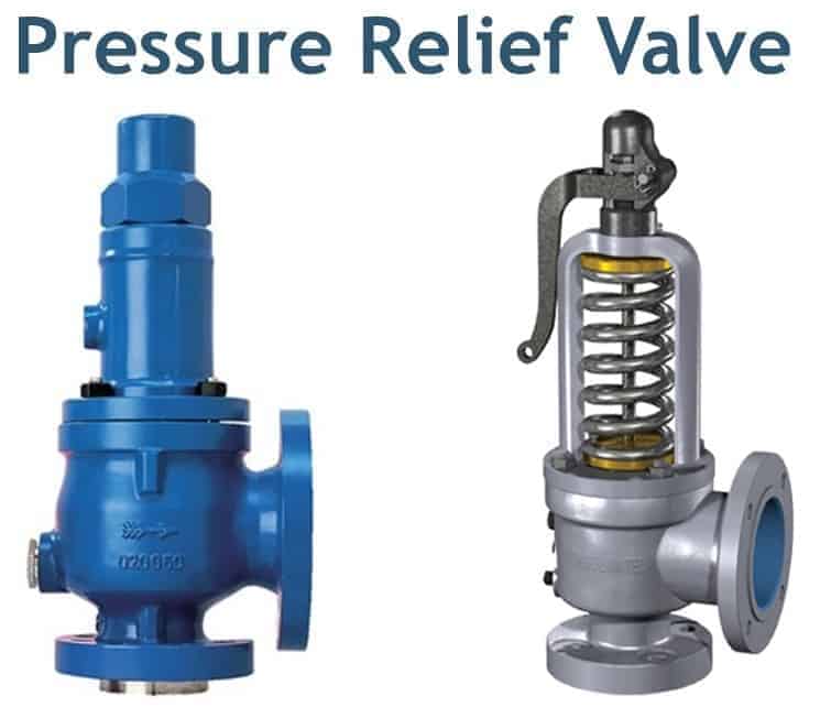
Valves Types based on Functions
The valve serves various functions within the piping system. Such as
- Stopping and starting a fluid flow. Depending on whether a valve is open or closed, it let pass the process fluid or halt the fluid.
- Throttling the fluid flow. Some of the valves let you throttle the fluid depending open % of the total opening. Lesser the opening higher the throttling and otherwise.
- Controlling the direction of fluid flow. The multiport valve lets you decide the way fluid will go.
- Regulating a flow or pressure within the piping system. Some of the automatic control valves maintain the flow and pressure within the system by adjusting opening and closing.
- Relieve pressure or vacuum from the piping system and equipment. Pressure and vacuum relief valve safeguard the process system from overpressure and during vacuum conditions.
Different types of valves serve these functions. These valves can be classified or categorized based on;
- Function
- End connection
- How it operates
- Types of Actuator it used.
Classification of Valves Based on Function
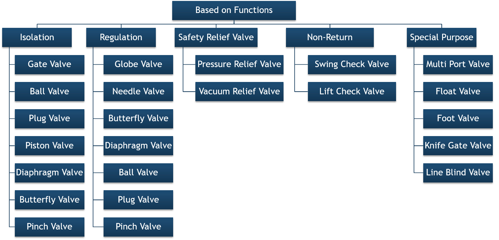
In the above chart, you can see the types of valves and their function.
Isolation valve isolates or cuts the supply of fluid when needed. Gate, ball, plug, piston, diaphragm, butterfly, and pinch valve falls under this category.
A control valve that regulates the flow of fluid falls in the regulation category. Globe, needle, butterfly, diaphragm, ball, plug, and pinch valve are used as a control valve. You can see that; some valves serve dual purposes such as the globe and the ball valve can be used as isolation as well as a control valve.
Pressure and vacuum relief valve used to prevent overpressure and vacuum with the system that can damage the piping and equipment. Non-return valve such as swing and lift check valve prevents backflow within the system. Whereas, some valves are designed to serve a special purpose. Such as multiport, knife, and line blind valve.
Classification of Valves Based on End Connections
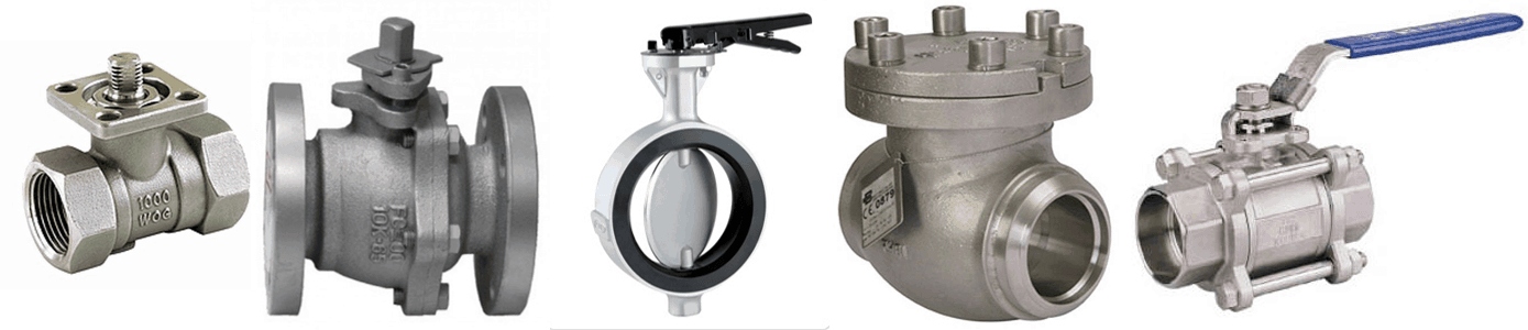
Based on the end connection, valve ends can be
- Screwed or threaded that connect with matching thread on the pipe. A small-bore valve used in instrument connection or as a sample point has a threaded end
- The majority valve used in piping has a Flanged type ends.
- Butt-welded valves are used in very high pressure and temperature services.
- Socket Welded valves are used in low-pressure
- Check valve and butterfly valves are available in wafer and lug end construction. These types of ends are used when space is constrained.
You can see the images of all these types of valve end above.
Classification of Valves Based on The Way it Open and Closed
| Valve type | Linear motion | Rotary motion | Quarter turn |
|---|---|---|---|
| Gate valve | X | ||
| Globe valve | X | ||
| Swing check valve | X | ||
| Lift check valve | X | ||
| Tilting-disc check valve | X | ||
| Folding-disc check valve | X | ||
| In-line check valve | X | ||
| Stop check valve | X | X | |
| Ball valve | X | X | |
| Pinch valve | X | ||
| Butterfly valve | X | X | |
| Plug valve | X | X | |
| Diaphragm valve | X | ||
| Safety valve | X | ||
| Relief valve | X |
Another way to classify the valve is the way it open and close. Each valve opens and closed by either Liner or rotary motion or by the quarter turn which is nothing but a rotary motion.
In the image below, you can see the difference between the opening methods of the valve.
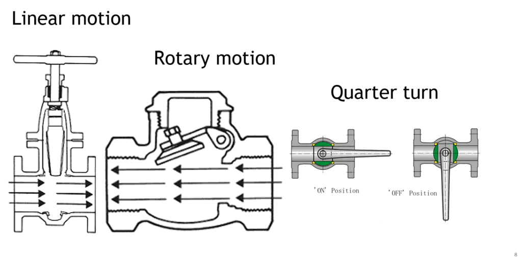
Linear motion valves use a closure member that moves in a straight line and cut the flow to start, stop, or throttle the flow. The closure device could be a disc, or flexible material, such as a diaphragm. Linear motion valves are slower in operation, but they provide a higher level of accuracy and stability in the position of the closure member.
Rotary motion valves rotate a disc or swing it from the hinge pin that holds the disk.
A 90° turn of the stem in Quarter-turn valves fully open or fully closed the valve. Because of this quick turn, the operation of the Quarter turn valve is much faster than linear motion valves. Some rotary motion valves are also known as the Quarter turn valve.
In the table, you can see that the ball valve, butterfly valve, and plug valve are both rotary and quarter-turn valves. Whereas swing check, tilting disk, and other rotary motion valves are not a quarter-turn valve.
Classification of Valves Based on Types of Actuator it Used
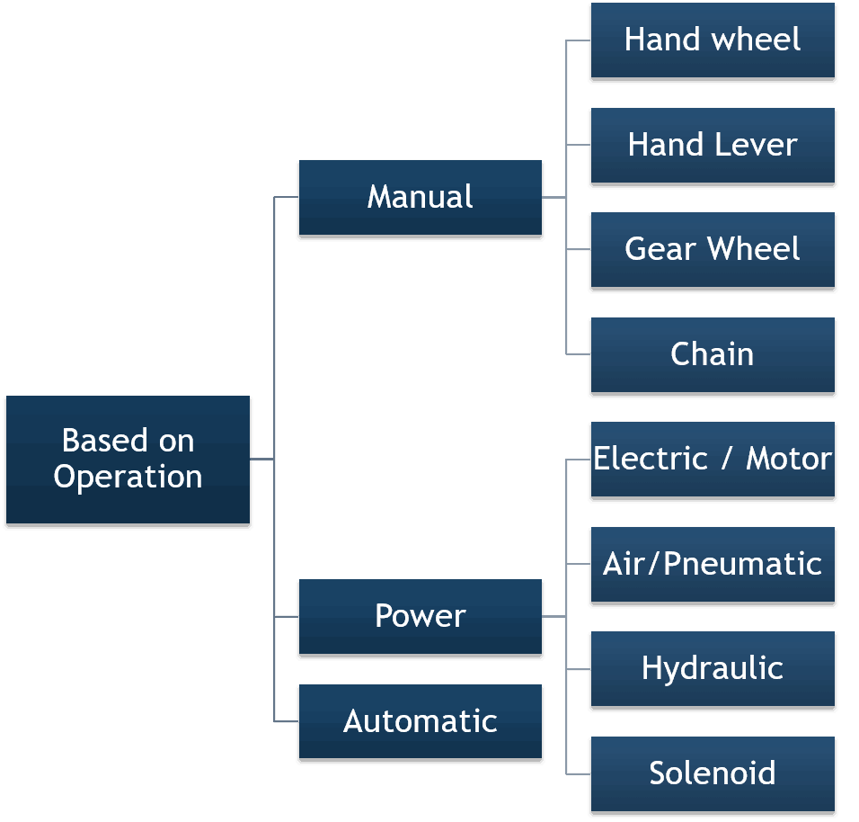
The last way to classify the valve is, types of the actuator is used to transfer the motion to operate the valve. The valve can be operated manually with the help of a handwheel, lever, chain, or by a gear wheel.
An external power source such as an electric motor, air, hydraulic fluid, or solenoid is used to operate a valve from the control room. The check valve works automatically when subjected to the backflow.
Types of Gate Valve and Parts – A Complete Guide for Engineer
What is Gate Valve?
A gate valve can be defined as a type of valve that used a gate or wedge type disk and the disk moves perpendicular to flow to start or stop the fluid flow in piping.
A gate valve is the most common type of valve used in any process plant. It is a linear motion valve used to start or stop fluid flow. In service, these valves are either in a fully open or fully closed position.
When the gate valve is fully open, the disk of a gate valve is completely removed from the flow. Therefore virtually no resistance to flow. Due to this very little pressure drops when fluid passes through a gate valve.
To achieve proper sealing, when the valve is fully closed, 360° surface contact is required between disk and seats.
Gate valves should not be used for regulation or throttling of flow because accurate control is not possible. The high velocity of the flow in the partially open valve may cause erosion of the disc and seating surfaces and also creates vibration and noise.
Gate Valve Parts
Here you can see the main parts of the gate valve. The disk of a gate valve is also known as a wedge. To learn about each of these parts read complete guide of valve parts.
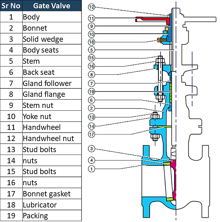
Types of Gate Valves
There are three ways to classify the gate valve.
- Types of Disk
- Solid taper wedge
- Flexible wedge
- Split wedge or Parallel disks Valve
- Types of Body Bonnet Joint
- Screwed Bonnet
- Bolted-Bonnet
- Welded-Bonnet
- Pressure-Seal Bonnet
- Types of Stem movement
- Rising Stem or OS & Y Type (Outside Stem and Screw Type)
- Non-rising Stem type
Solid Wedge Gate Valve
Solid wedge is the most common & widely used disk type because of its simplicity and strength. A valve with a solid wedge may be installed in any position, and it is suitable for almost all fluids. It can be used in turbulent flow also.
However, it does not compensate for changes in seat alignment due to pipe loads or thermal expansion. So, this type of disk design is most susceptible to leakage. Solid wedge is subjected to thermal locking if used in high-temperature service.
Thermal locking is a phenomenon in which wedge is stuck between the seats due to the expansion of the metal. Solid-wedge gate valves are generally used in moderate to lower pressure-temperature applications.
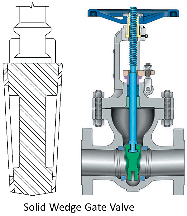
Flexible Wedge Gate Valve
The flexible wedge is a one-piece solid disk with a cut around the perimeter. These cuts vary in size, shape, and depth. A shallow, narrow cut on wedge perimeter gives less flexibility but retains strength. A cast-in recess or deeper and wider cut on wedge perimeter gives more flexibility but compromises the strength.
This design improves seat alignment and offers better leak tightness. It also improved performance in situations where thermal binding possible. Flexible wedges Gate valves are used in steam systems.
Thermal expansion of the steam line sometime causes distortion of valve bodies which may lead to thermal blinding. The flexible gate allows the gate to flex as the valve seat compresses due to thermal expansion of the steam pipeline and prevents thermal blinding.
The disadvantage of flexible gates is that line fluid tends to collect in the disk. These may result in corrosion and ultimately weaken the disk.
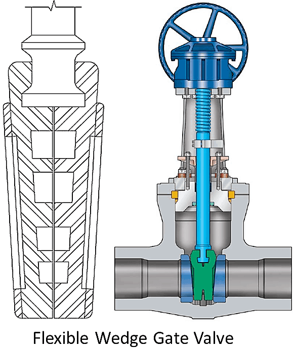
Split wedge or Parallel disks Gate Valve
Split wedge Disk consists of two solid pieces and holds together with the help of a special mechanism. You can see the same in images. In case, one-half of the disk is out of alignment; the disk is free to adjust itself to the seating surface. The split disk can be in a wedge shape or a parallel disk type.
Parallel disks are spring-loaded, so they are always in contact with seats and give bi-directional sealing. The split wedge is suitable for handling noncondensing gasses and liquids at normal and high temperatures.
Freedom of movement of the disk prevents thermal binding even though the valve may have been closed when a line is cold. This means when a line is get heated by fluid and expand it does not create thermal blinding.
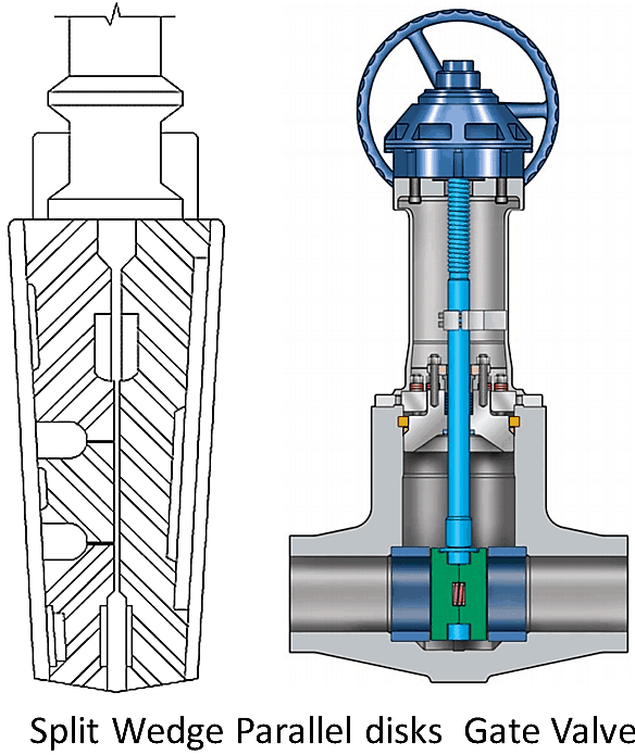
Types of gate valve based on body, bonnet connection
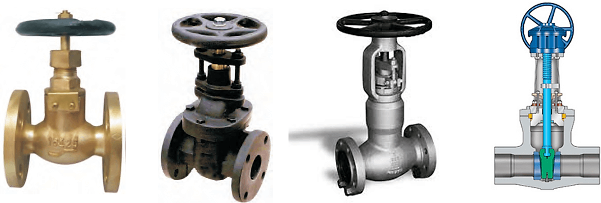
1st is screwed bonnet: This is the simplest design available and it is used for inexpensive valves.
2nd is bolted-bonnet: This is the most popular design and used in a large number of gate valves. This requires a gasket to seal the joint between the body and bonnet.
3rd is Welded-Bonnet: This is a popular design where disassembly is not required. They are lighter in weight than their bolted-bonnet counterparts.
4th one is Pressure-Seal Bonnet: This type is used extensively for high-pressure high-temperature applications. The higher the body cavity pressure, the greater the force on the gasket in a pressure -seal valve.
OS & Y Gate Valve or Rising Stem (Outside Stem and Screw Type)
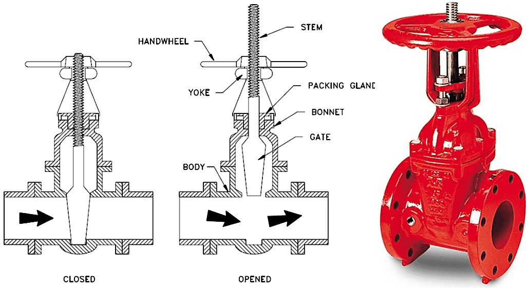
For a rising stem valve, the stem will go up while opening the valve and move down when you close the valve. You can see in the image. In inside screw design, the threaded portion of the stem is in contact with the flow medium, and when you open the valve, handwheel rise with the stem.
Whereas in the case of outside screw design, the only smooth portion is exposed to the flow medium and the stem will rise above the handwheel. This type of valve is also known as OS & Y valve. OS & Y means outside steam and York.
Non-rising Stem Gate Valve or Insider Screw Valve
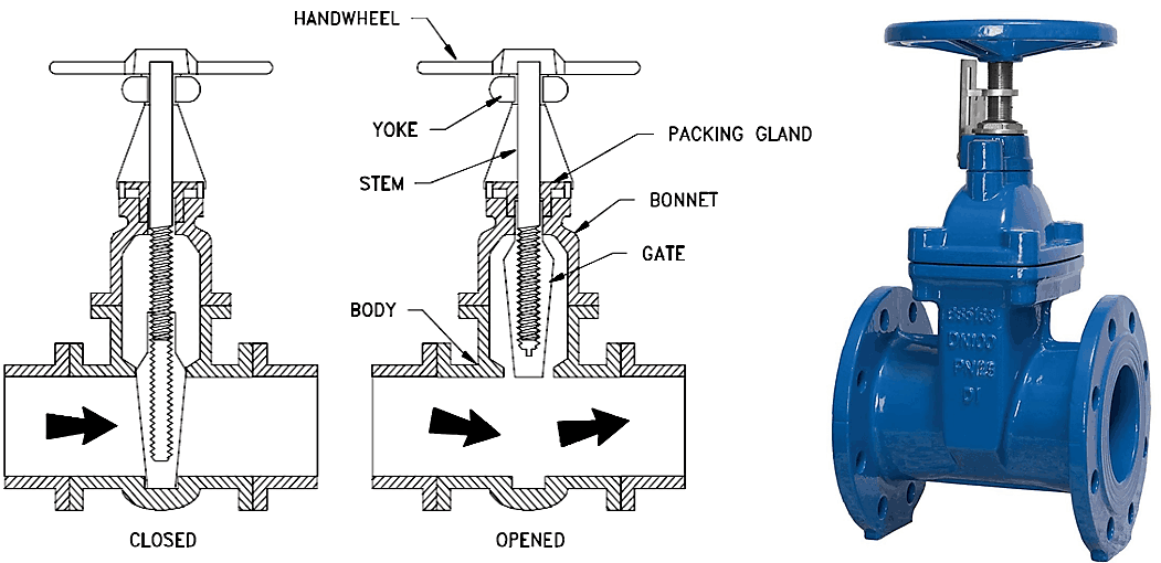
There is no upward movement of the stem in a non-rising stem type. The valve disk is threaded internally. The disc travels along the stem like a nut when the stem is rotated. You can see the image. In this type of valve, stem threads are exposed to the flow medium.
Therefore, this design is used where space is limited to allow linear stem movement, and the flow medium does not cause erosion, corrosion, or wear and tear to stem material. This type of valve also known as an insider screw valve.
Gate Valve Applications
- Gate valves are used in almost all fluid services such as air, fuel gas, feedwater, steam, lube oil, hydrocarbon, and all most any services.
- Some special gate valve is used in slurry and powder product also such as knife gate valve
Advantages of Gate Valve
- Gate valve provides good
- Pressure drop during operation is very less.
- Most of the gate valve can be used as bi-directional
- They are suitable for high pressure and temperature application and required less maintenance
Disadvantages of Gate Valve
- It cannot be used to control the flow.
- A gate valve is slow in operation. Opening and closing take time which is good also as it reduces the chance of hammering.
- When partially open it creates vibration and noise.
- Repairs, such as lapping and grinding of seats are more difficult due to limited access.
Globe Valve Types and Parts – A Complete Guide
What is Globe Valve?
A globe valve is a linear motion valve used to stop, start, and regulate the fluid flow. The globe valve disk can be removed entirely from the flow path, or it can completely close the flow path. During the opening and closing of the valve, the disc moves perpendicularly to the seat.
This movement creates the annular space between the disk and seat ring that gradually closes as the valve closed. This characteristic provides the globe valve good throttling ability required for regulating the flow.
Leakage from the globe valve seat is less as compared to the gate valve, mainly due to right angle contact between the disc and seat ring, which allows tighter seal between seat the disk.
Globe Valve Diagram
In the below globe valve diagram, you can see how the globe valve functions. The image also shows flow direction.
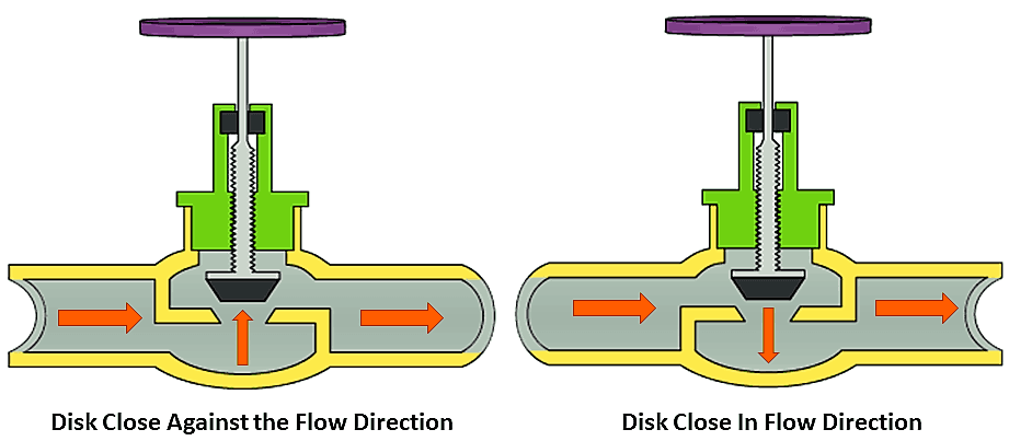
Globe valves can be arranged in such a way that the disk closes against the flow or in the same direction of flow.
When the disk closes in the direction of flow, the kinetic energy of the fluid helps closing but obstructs the opening. This characteristic is preferable when a quick-acting stop is required.
When the disk closes against the direction of flow, the kinetic energy of the fluid obstructs closing but helps to open the valve. This characteristic is preferable when quick-acting start is required.
Globe Valve Parts
Here in below image, you can see the globe valve parts such as Body, Bonnet, Stem, Seat, Disk, etc.
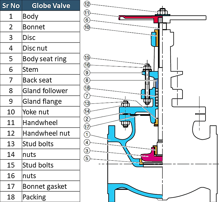
Globe Valve Disk Types
Globe valve is available in many different types of disc arrangement. The most used disk designs are listed below.
- Ball Type
- Needle Type
- Composite type

The ball disk design is used in low-pressure and low-temperature systems. It is capable of throttling flow, but in principle, it is used to stop and start the flow.
Needle disk design provides better throttling as compared to ball or composition disk design. A wide verity of long and tapered plug disks are available to suit different flow conditions.
Composition disk is used to achieve better shutoff. A hard, non-metallic insert ring is used in composition disk design.
Types of Globe Valve
Depending on the type of body there are three types of globe valves;
- Z types
- Y types
- Angle Types
Z types Globe Valve
The simplest design and most common type is a Z-body. The Z-shaped partition inside the globular body contains the seat. The horizontal seating arrangement of the seat allows the stem and disk to travel at a perpendicular to the pipe axis resulting in a very high-pressure loss.
The valve seat is easily accessible through the bonnet which is attached to a large opening at the top of the valve body. Stem passes through the bonnet like a gate valve.
This design simplifies manufacturing, installation, and repair. This type of valve is used where pressure drop is not a concern and throttling is required.
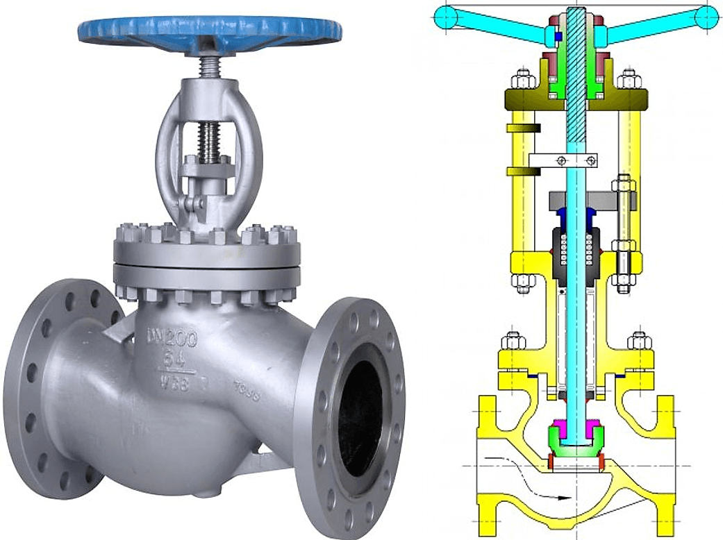
Y types Globe Valve
The Y-type design is a solution for the high-pressure drop problem in Z-type valves. In this type, seat and stem are angled at approximately 45° to the pipe axis. Y-body valves are used in high pressure and other critical services where pressure drop is concerned.
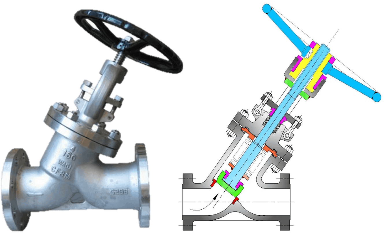
Angle types Globe Valve
Angle globe valve turns the flow direction by 90 degrees without using an elbow and one extra pipe weld. Disk open against the flow. This type of globe valve can be used in the fluctuating flow condition also, as they are capable of handling the slugging effect.

Globe Valve Types based on Body Bonnet Connection
Screwed bonnet: This is the simplest design available and it is used for inexpensive valves.
Bolted-bonnet: This is the most popular design and used in a large number of globe valves. This requires a gasket to seal the joint between the body and bonnet.
Welded-Bonnet: This is a popular design where disassembly is not required. They are lighter in weight than their bolted-bonnet counterparts.
Pressure-Seal Bonnet: This type is used extensively for high-pressure high-temperature applications. The higher the body cavity pressure, the greater the force on the gasket in a pressure -seal valve.
Application of Globe valve
Globe Valves are used in the systems where flow control is required and leak tightness is also important.
- It used in high-point vents and low-point drains when leak tightness and safety are major concerns. Otherwise, you can use a gate valve for drain and vent.
- It can be used in Feed-water, chemical, air, lube oil and almost all services where pressure drop is not an issue
- This valve is also used as an automatic control valve, but in that case, the stem of the valve is a smooth stem rather than threaded and is opened and closed by lifting action of an actuator assembly.
Advantages
- Better shut off as compared to gate valve
- Good for frequent operation as no fear of wear of seat and disk
- Easy to repair, as seat and disk can be accessed from the valve top
- Fast operation compares to gate valve due to shorter stroke length
- Usually operated by an automatic actuator
Disadvantages
- High head loss from two or more right-angle turns of flowing fluid within the valve body.
- Obstructions and discontinuities in the flow path lead to a high head loss.
- In a large high-pressure line, pulsations and impacts can damage internal trim parts.
- A large valve requires considerable power to open and create noise while in operation.
- It is heavier than other valves of the same pressure rating.
- Costlier compared to the gate valve.
What is a Check Valve? Learn about Check Valves Types and Parts
What is a Check Valve?
The valve that used to prevent backflow in a piping system is known as a check valve. It is also known as a non-return valve or NRV. The pressure of the fluid passing through a pipeline opens the valve, while any reversal of flow will close the valve.
It allows full unobstructed flow and automatically shuts as pressure decreases. The exact operation will vary depending on the mechanism of the valve.
Parts of Non-Return Valve
It is consists of body, cover, disk, hinge pin, and seat ring. In the image below you can see the parts of the valve.
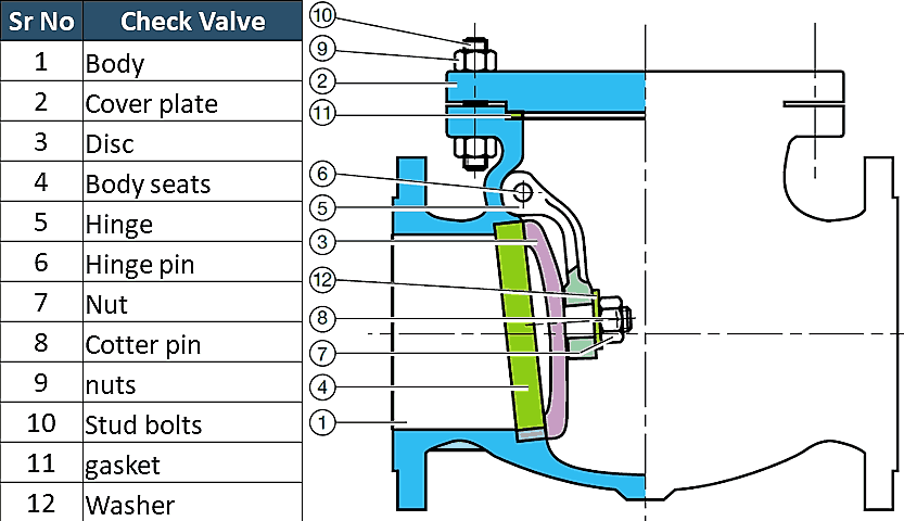
Types of Valves
The type of disk will decide the type of valve. Most common types of Check valves are
- Swing Type.
- Top Hinged
- Tilting disk
- Lift Type
- Piston Type
- Ball type
- Dual Plate Type
- Stop Check Valve
Let’s learn about each of them.
Swing Check Valve
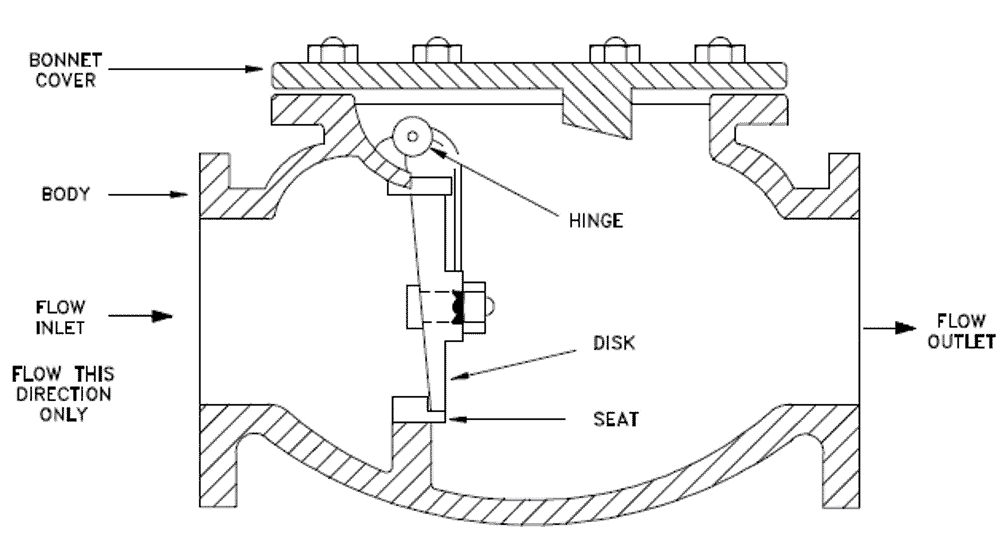
The disc in a swing type valve is unguided as it fully opens or closes. This Valve operates when there is flow in the line and get fully closed when there is no flow. Turbulence and pressure drop in the valve is very low. Disk and seat designs can be of metal to metal or metal to composite.
The angle between the seat and the vertical plane is known as the seating angle and varies from 0 to 45 degrees. Usually, the seat angles are in the range of 5 to 7 degrees. Larger seat angles reduce the disc travel, resulting in quick closing, thus minimizing the possibility of water hammer. A vertical seat has a 0-degree angle.
The swing type valve allows full, unobstructed flow and automatically closes as pressure decreases. Usually installed in combination with gate valves because they provide relatively free flow combinations.
A basic swing type valve consists of a valve body, a bonnet, and a disk that is connected to a hinge.
Tilting Disc Check Valve
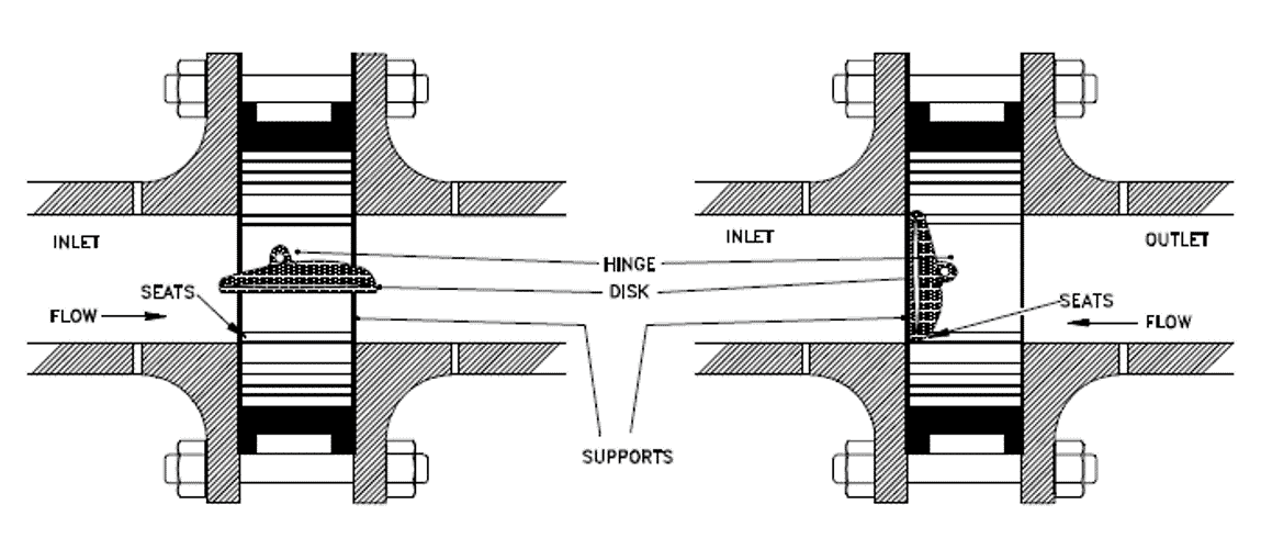
The tilting disc type valve is designed to overcome some of the weaknesses of conventional swing type valves. The design of the tilting disk enables the valve to open fully and remain steady at lower flow rates and close quickly when the forwarding flow stop.
The dome-shaped disc floats in the flow and fluid flow on both the bottom and top of the disk surfaces. As the disk is spring-loaded, when forward flow pressure reduces, the spring force helps the valve to close fast. In the image above, you can see the flow from the valve.
Tilting Disc type Valve is available in wafer type and lug type design.
Ball Type and Plug Type Lift NRV
The seat design of a lift Check valve is similar to a Globe valve. A piston or a ball is usually used as a disk.
Lift Check valves are particularly suitable for high-pressure service where the velocity of flow is high. The disk is perfectly set on the seat with full contact. They are suitable for installation in horizontal or vertical pipelines with upward flow.
When the flow enters below the seat, a disk is raised from the seat by the pressure of the upward flow. When the flow stops or reverses, the backflow and gravity forced the disk downward to set on the seat. Commonly used in piping systems that used globe valves as a flow control valve.
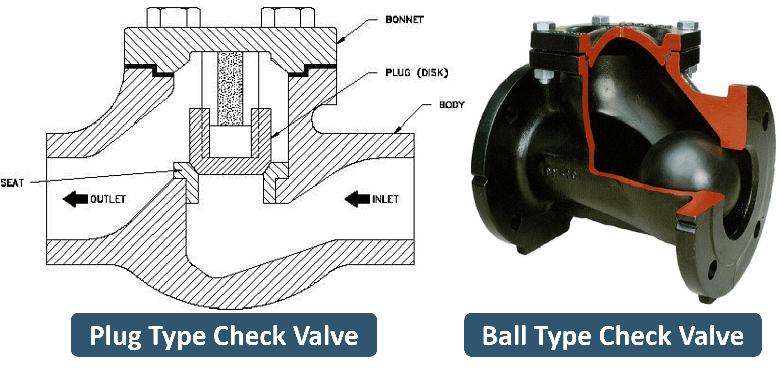
Here you can see the plug or piston type and ball type check valve. These valves provide superior leak-tight characteristics to those of swing check valves.
Some design in plug type uses spring to retain the disk in a closed position. This will ensure that the valve allows fluid flow only when there is enough pressure in the flow direction.
A ball-type valve is very simple as it simply works on the principle of gravity. When there is enough pressure in the flow, it lifts the ball upward but when pressure reduced ball roll down and closed the opening.
Dual Plate / Dual Disc Check Valve
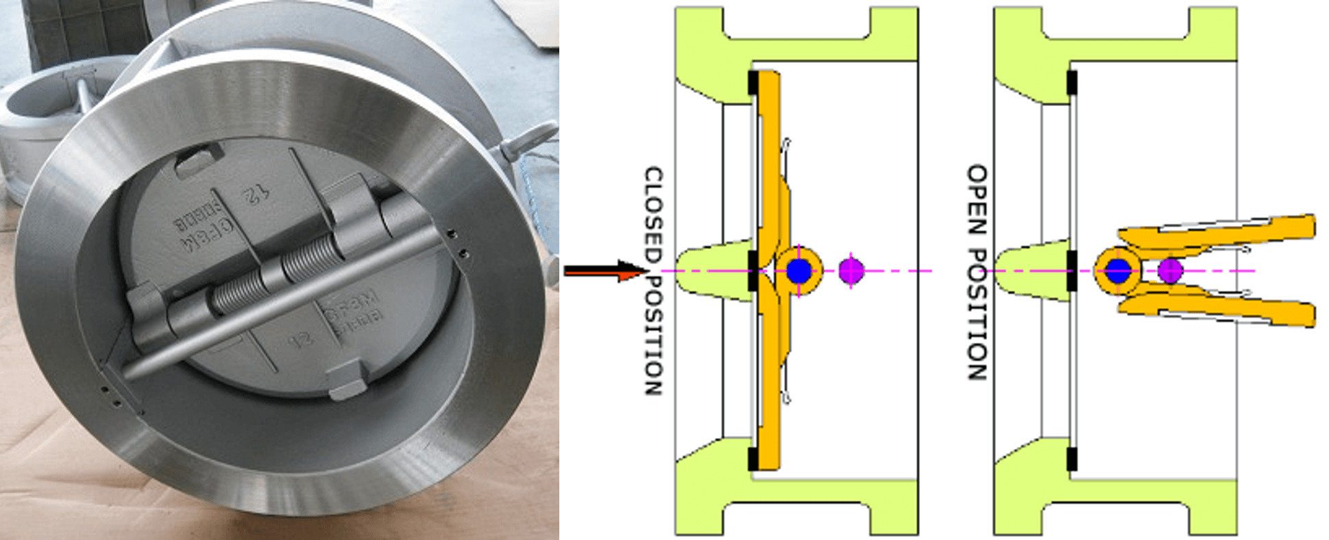
A dual plate check valve is known as a butterfly check valve, Folding Disc Check Valves, double-disc, or splits disc check valve. As the name suggests, two halves of the disk move towards centreline with the forward flow and with reverse flow two halves open and rest on the seat to close the flow (Flapping action).
Use of Dual Plate Check Valve is popular in low-pressure liquid and gaseous services. Its lightweight and compact construction make it a preferable choice when space and convenience are important.
It is 80 to 90% lighter than the conventional full body check valve. Frequently used in systems that used butterfly valves. The cost of installation & maintenance is very low compared to other types.
Stop Check Valve
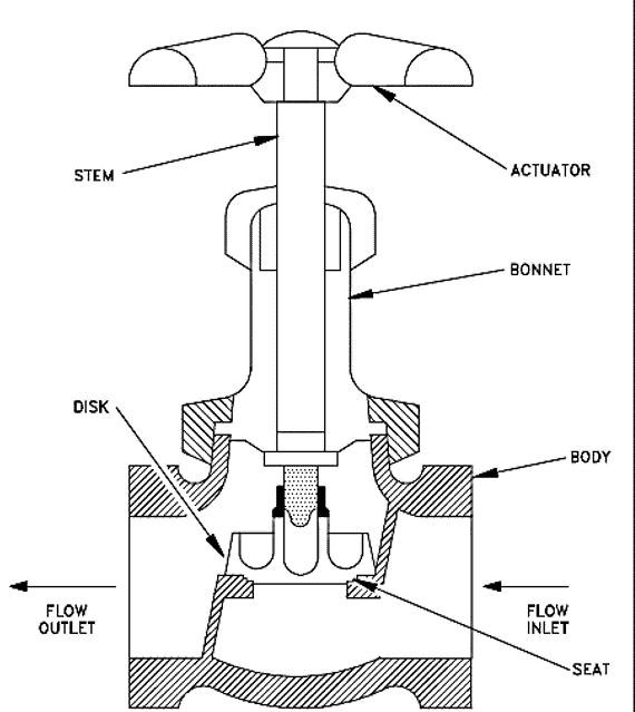
Stop Check Valve is a combination of a lift check valve and a globe valve. It can either be used as a check valve or as an isolation (stop) valve like a globe valve. These valves can be closed with the help of a stem that is not connected to the valve disc during normal operation and make it possible to use these valves as a regular NRV.
However, when needed, the stem is used to holds the free-floating disc against the valve seat, just as a globe valve. These valves are available in tee, wye, and angle patterns. Swing type and piston lift type valves are commonly used as stop check valves.
Application of Check Valve (NRV)
Check valves (Non-return valve) are used in a piping system to prevent backflow. The discharge line of rotary equipment such as pump and compressor always fitted with a check valve to prevent backflow.
Advantages & Disadvantages
Can you guess why I have not mentioned any advantages or disadvantages of the check valve?
The only function of a Non-return valve is to prevent backflow. There is no better alternative. Yes, you can choose the best NRV from the various available type that you have learned but you cannot supplement the Non-return valve with another valve.
What is Plug Valve? – A Complete Guide for Engineer
What is Plug Valve?
Plug valve is a Quarter-turn rotary motion Valve that uses a tapered or cylindrical plug to stop or start the flow. The disk is in plug shape, which has a passage to pass the flow.
In the open position, this bored passage is in line with the flow. When the plug is turned 90° from the open position, the solid part of the plug blocks the flow.
It is used in place of a gate valve where the quick operation is required. It can be used in high-pressure temperature services.
Types of Plug Valves
These valves are available in either a lubricated or non-lubricated design and with different styles of port openings through the plug.
Lubricated Plug Valve
The plug inside a lubricated plug valve has a cavity in the middle along its axis. You can see this in the image. Lubricant chamber at the bottom and the sealant injection fitting at the top ensure the supply of lubricant.
The small check valve below the injection fitting prevents the sealant from flowing in the reverse direction once the sealant is injected into the cavity.
Plug surface gets constantly lubricated by the sealant that moves from the center cavity through radial holes into lubricant grooves on the plug surface. Now why we required all this? Many plug valves are of all-metal construction.
The narrow gap around the plug may allow leakage, and if you reduce the gap further, it will increase the friction and plug may get stuck inside the valve body.
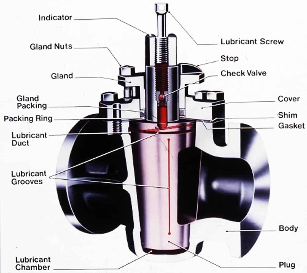
The lubricant reduces the force required to open or close the valve and allows smooth movement of the plug. It also prevents corrosion of the plug.
The lubricant material must be compatible with the fluid of the pipeline. It should not dissolve or wash away by the flow medium as this could contaminate the fluid, and damage the seal between the plug and the body, resulting in leakage. Also, the sealant used must be able to withstand the temperature of the flow medium.
Lubricated plug valves are available in the large size range, and they are fit to work in high-pressure temperature services. These valves are subject to less wear and provide better corrosion resistance in some service environments.
Non-lubricated Plug Valves
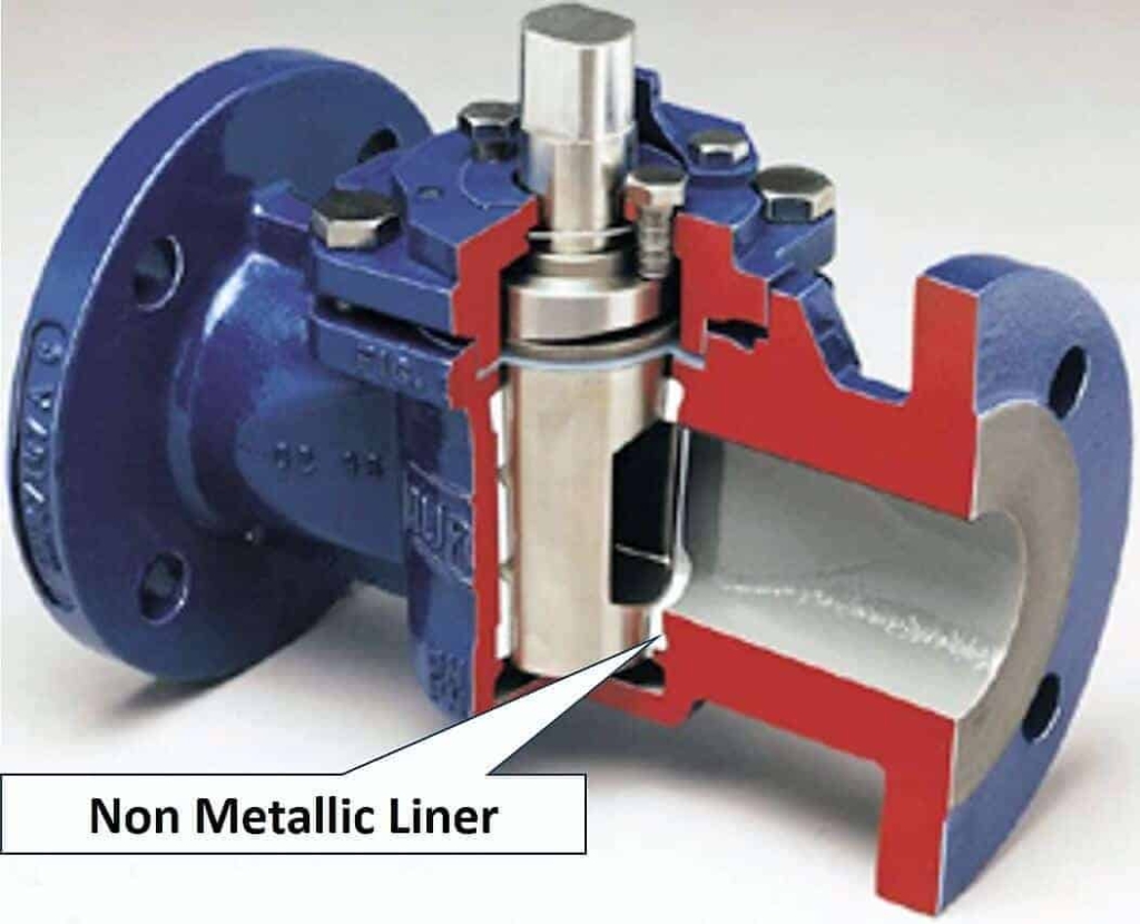
A non-metallic elastomeric sleeve or liner is used in this type of valve. This sleeve is installed in the body cavity of the valve. The polished tapered plug acts as a wedge and presses the sleeve against the body.
This nonmetallic sleeve reduces the friction between the plug and the valve body. Non-lubricating plug valves required minimum maintenance. Due to the non-metallic seat, these valves are not used in high-temperature services.
Lubricating and non-lubricating valves are capable of providing a bubble-tight shutoff and are of compact size.
Multi-Port Plug Valves
Here you can see the 3-way multiport plug valve. The top image is of 3-way 3-port design and the bottom is 3-way 2-port design.
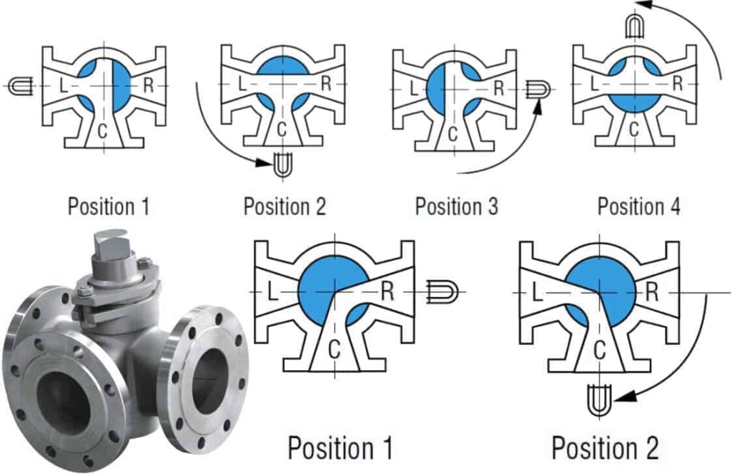
Image below shows 4-way design.
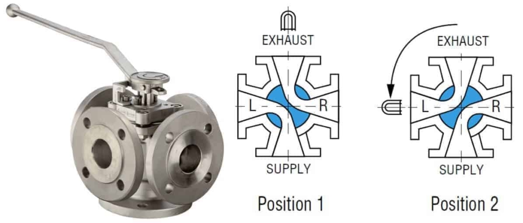
Multiport valves are used in transfer lines and for diverting services. A single multiport valve may serve the purpose of three or four gate valves or other types of the shutoff valve.
However, sometimes the multiport valve does not completely shut off flow. Great care should be taken in specifying the particular port arrangement for proper operation.
Plug Valve Parts
The typical plug valve is consisting of a body, bonnet, stem, and plug. The seat is an integral part of the body in case of a lubricated type. For a non-lubricated type, a non-metallic seat is used to improve leak tightness of the valve.
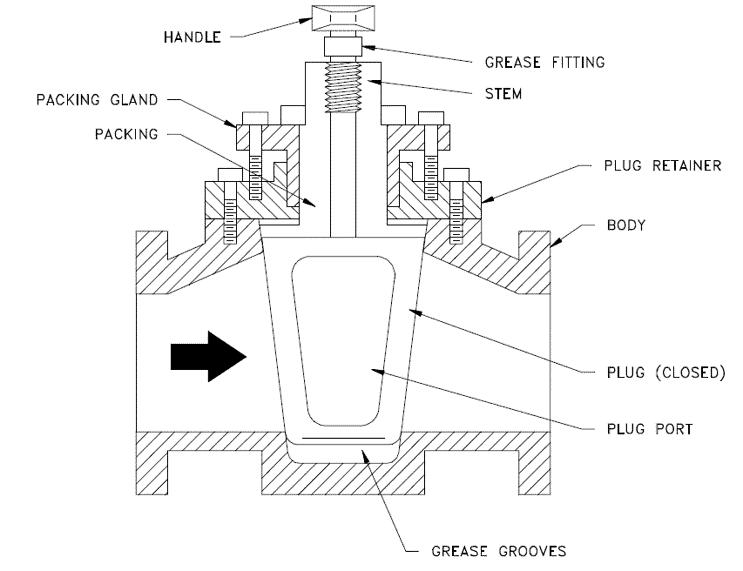
Plug Valve Disk Types
Plugs are either round or taper cylinder. They may have various types of port openings, each with a varying degree of the opening area.
Plugs are available with
- Rectangular Port
- Round Port and
- Diamond Port
Here in the image, you can see the taper plug with Rectangular, Round, and Diamond Port design.
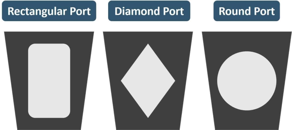
- Rectangular Port is the most common for a plug valve. The rectangular port represents at least 70% of the corresponding pipe’s cross-sectional area.
- Round port plug has a round opening through the plug. It is available in full bore and reduced bore design. Valves with reduced ports are used only where restriction of flow is not important.
- Diamond Port plug has a diamond-shaped port through the plug. All diamond port valves are venturi restricted flow type. This design is for throttling service.
Application of Valve
- This valve is used as on-off stop valves and capable of providing bubble-tight shutoff.
- It can be used in different types of fluid services such as Air, gaseous, vapor, Hydrocarbon, slurries, mud, and sewage applications.
- Also used in a vacuum to high-pressure & temperature applications
Advantages
- Simple design with few parts
- Quick to open or close
- inline maintenance possible
- Offers minimal resistance to flow
- Provides reliable leak-tight service
- Multiple port design helps reduce the number of valves needed and permits a change in a flow direction
Disadvantages
- It requires greater force to operate, due to high friction
- Larger valves cannot be operated manually and required an actuator
- Pressure drop due to reducing port
- Cost of Plug valves may be more than ball valves for given size and class
Learn about 6 Types of Ball Valve – Floating, Trunnion Mounted & more
A Ball valve is a quarter-turn rotary motion valve that uses a ball-shaped disk to stop or start the flow. It resembles a plug valve in many ways. When a port in the ball is in line, it allows flow whereas when you rotate the valve 90 degrees, solid part of the ball stop the flow.
Most ball valves are of the quick-acting type, which requires a 90° turn of the valve handle to operate the valve. But in case large size valve which required considerable force to open or close the valve, the gear-operated actuator is used. With this arrangement, a small handwheel is enough to operate a fairly large valve.
In this article, I have covered following types of Ball Valves that used in piping.
- Floating
- Trunnion Mounted
- 3 Way
- Top entry
- Side entry or split body
- Three-piece body
Check this video for the better understanding on this topics.
Floating Ball Valve
In a floating ball valve, the ball is held in the position by the compression of the two elastomeric seats against the ball. The ball is free to float inside the valve body. See the highlighted portion in the image and remember as you will see the difference when I will explain to you about the trunnion mounted valve.
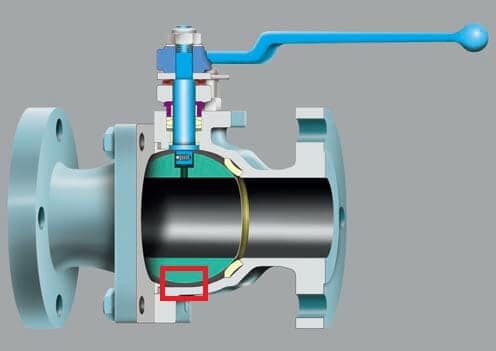
The stem is connected to a slot at the top of the ball which allows the ball to rotate a quarter turn (90 degrees). The shaft allows for a certain amount of lateral movement of the ball that is generated from the upstream pressure acting on the ball. This small lateral movement, in fact, produces a load on the ball that presses it against the downstream seat which improves leak tightness of valve. This type of valve design is capable of bi-directional shut-off. The floating valve is very difficult to operate when upstream pressure is high. You can see the image of a floating type valve.
Check the video below to learn how this floating type valve works.
Trunnion Mounted Ball Valve
Trunnion mounted valve is a solution to the problem of excessive torque required by a floating type valve in high-pressure service. A short shaft like an extension which is known as a trunnion set in the body. You can see this in the image. In this design steam and ball work as a single unit. The ball is supported by two floating or spring-loaded seats that remain in constant contact with the ball.
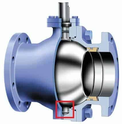
Trunnion ball design required a lower operating torque. Hence, reduces the size of the actuator and overall costs of the valve. This cost difference becomes an important factor when the pressure class and valve size increases. Check the video below for an animation of this type of valve.
Check this video to know how Trunnion Mounted Ball Valve works.
3 Way Ball Valve
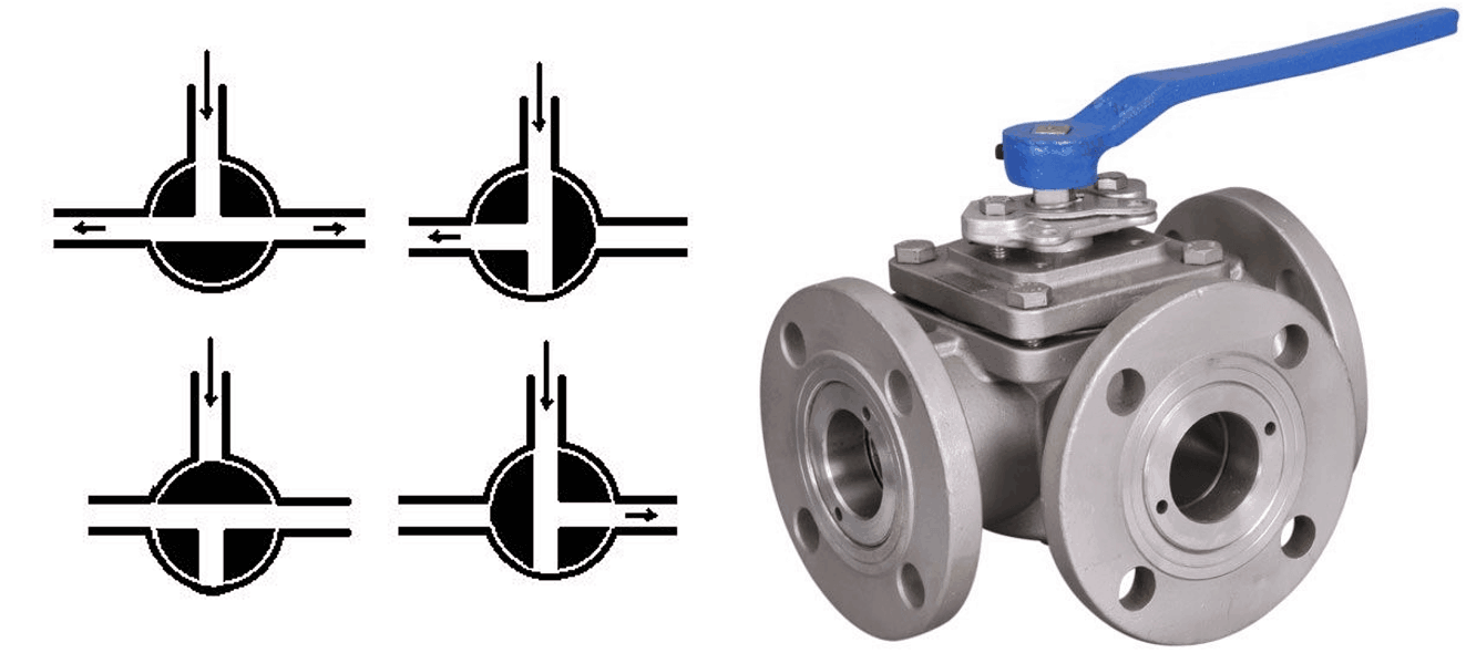
Depending on your requirements, you can arrange the port of valve in the three-way.
- One inlet and two distribute
- One inlet and one outlet with diverting a flow
- Stright pass the fluid without No inlet
Three patterns are available. Venturi port type, full port type, and reduced port type. The full-port ball valve has an inside diameter equal to the inside diameter of the pipe. This design allows pigging. In the venturi and reduced-port types, the port is generally one pipe size smaller than the line size.
The ball type disc can be a free float or fixed in the valve body. A free-floating valve is known as a floating type whereas a fixed type valve is known as a trunnion mounted valve.
Types of Ball Valves based on Body Construction
Ball valves are manufactured in different body arrangements. Based on this valve can be classified in the following ways;
- Top entry
- Side entry or split body
- Three-piece body
For Extremely high pressure and temperature services, the full welded body is also used.
Top-Entry Ball Valve
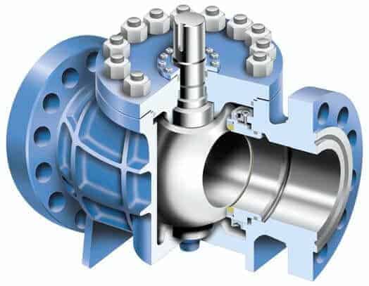
As you can see in the image above, removing bonnet cover of top entry valves, allows access to valve internals for assembly, disassembly, repair, or maintenance without removing the valve from the pipeline.
Split-Body Ball Valve
In this design, a valve body is divided into two or three body parts. A ball, seat rings, stem, and other internals set inside the larger body part and held together with smaller parts by bolting.
For a split body, two pieces valve, refer floating ball valve image. Refer below image for split body three pieces type valve.
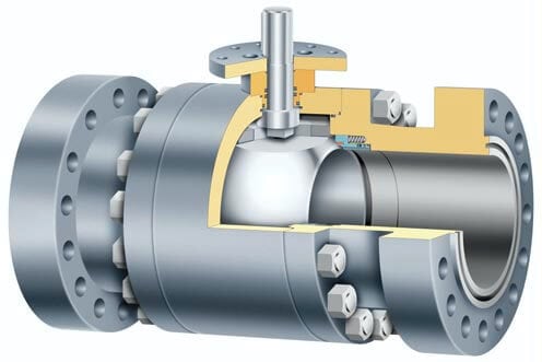
Ball Valve Parts
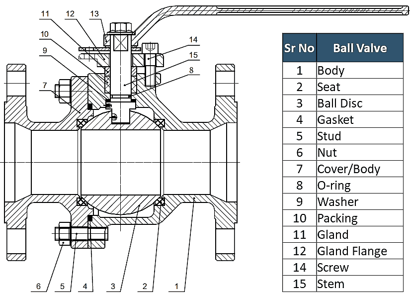
Major components of the valve are the body, spherical ball, steam, and seats. It can be metal seated or soft seated. This valve may be unidirectional, bidirectional, or multidirectional, depending on the number of valve ports and the number of valve seats. Same as multiport plug valve. In the image below, you can see the 3-way ball valve.
Applications of the Valve
- It can be used in different types of fluid services as an on-off stop valve that provides bubble-tight shutoff.
- It can be used in air, gaseous, and vapor services as well as hydrocarbon services.
- Metal seated valves can be used in high-pressure & temperature applications.
- it is widely used with instrument tubing to connect instruments.
Advantages
- It is quick to open and close type that provides bubble-tight reliable sealing in high-pressure temperature applications.
- It is smaller and lighter than a gate valve of the same size and rating.
- Several designs of ball valves offer the flexibility of selection so that you can choose the valve that suits your requirements.
- Easy to operate and Cost-effective maintenance.
Disadvantages
- It cannot be used in service that required throttling.
- In slurry or other similar applications, the suspended particles can settle and become trapped in body cavities causing wear, leakage, or valve failure.
- Due to rapid opening and closing, surge pressures may arise which could damage downstream equipment.
Butterfly Valve Types – Wafer, Lug, Double Offset and Triple Offset Types
A Butterfly valve is a quarter-turn rotary motion valve, that is used to stop, regulate, and start the flow. Butterfly valves are a quick open type. A 90° rotation of the handle can completely close or open the valve. Normally, they are used in systems where a positive shut-off is not required. In this article, you will learn about following types of Valve.
- Wafer Type
- Lug Style Type
- Flanged Type
- Butt Welded Ends Types
- Zero offset
- Double Offset
- Triple Offset
Large Butterfly valves are usually equipped with gearbox type actuator, where the handwheel is connected to the stem via a gearbox. This will reduce the force but at the same time reduce the speed of the operation. This type of valve should be installed in the open position. If the valve is closed during installation, the rubber seat will wedge against the valve disc and make it difficult to open.
Types of Butterfly Valves Based on Body Construction
Based on the type of ends of the body butterfly valves are available in following types.
- Both Flanged Ends
- Wafer Type Ends
- Lug Type Ends
- Butt Welded Types Ends
Wafer Types
The wafer body is placed between pipe flanges, and the flange bolts surround the valve body. A wafer type butterfly valve is easy to installed but it cannot be used as an isolation valve.
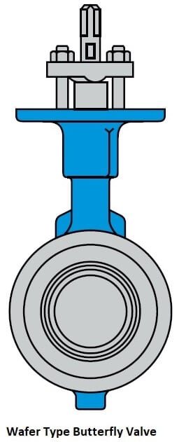
Lug Style
The lug body has protruding lugs in the periphery of a body that provides passage to bolt holes that match with those in the flanges.
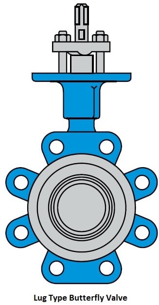
Flanged Type
In this types, the body has flanged that match with pipe flange dimension.
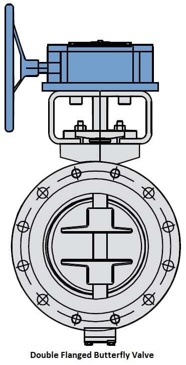
Butt Welded Ends Types
This types of ends are used in high-pressure services and it directly welded to the pipe.
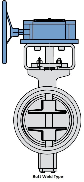
Zero offset Butterfly Valve
Zero offset design used for the valve that used in low-pressure and temperature services. In this design, the disc and shaft axis is concentric with the valve body. In the open position, the disc divides the flow into two equal halves, with the disc in the middle and parallel to the flow.
This type of valve has a resilient seat. Sealing is achieved when the disc deforms the soft seat. There is friction between the disk and seat during the full operating cycle which is the disadvantage of zero offset valve.
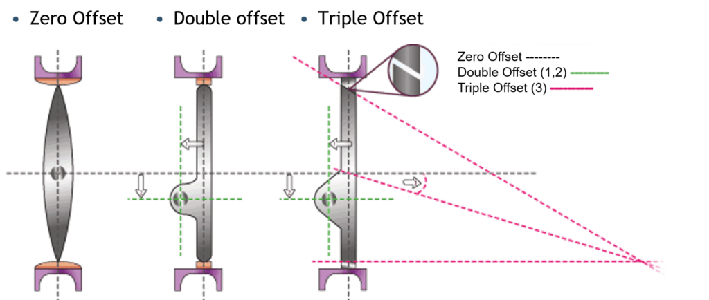
Double Offset Butterfly Valve
In Double Offset, the disk is offset from the valve center line and also from valve body center line. You can see this in the image where one and two are written. This creates a cam action during operation that lifts the seat out of the seal.
Double offset makes opening and closing smooth as friction is applicable only during the first few degrees of opening and final few degrees of closing, approx 10 degrees of opening and closing.
Triple Offset Butterfly Valve
In Triple Offset design the third offset created by the geometry design of the seating surface. The seat is machined into an offset conical profile resulting in a right-angled cone. You can see this in the third image with small enlargement of seating angle.
This ensures frictionless stroking throughout its operating cycle. Contact is only made at the final point of closure with the 90° angle acting as a mechanical stop; the Metal seated valve uses triple offset design.
Butterfly Valve Body Parts
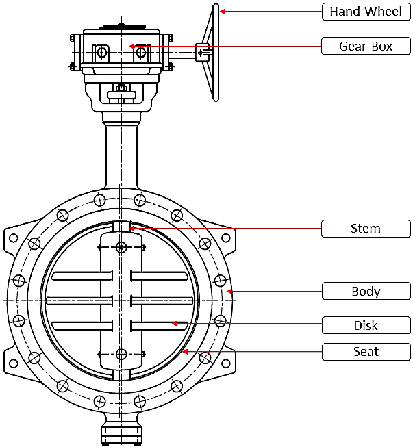
The typical butterfly valve has a short circular body, a round disk, shaft, and metal or soft seats. You can see the parts in the above image. Check the video below for the functioning of the valve.
Seat Types
Butterfly valves can be metal-to-metal seated, soft seated, or with a fully lined body and disc. The first image is of a soft seated fully lined body and disc valve. Second, is a soft seat with metal disk and the third is metal to metal seat type valve.
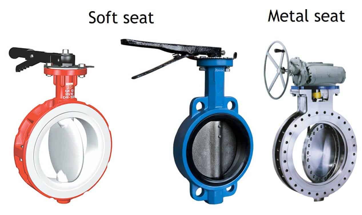
The disk of butterfly valve can be concentric or eccentric with the valve body. Here I have shown three different arrangements of the disk with respect to a center of the valve body.
Applications
- A Butterfly valve is used in many different fluid services and they perform well in slurry applications also. They can be used in liquids, steam, cryogenics, cooling water, air, gasses, firefighting & Vacuum services.
- Butterfly Valve is used in all type of industries application even in High-pressure and temperature services.
Advantages
- Butterfly Valve is suitable for large valve applications due to Compact, lightweight design that requires considerably less space, as compared to other valves
- Due to a quick operation, it needs less time to open or close
- The maintenance costs are usually low compared to other valve types
- A pressure drop across a butterfly valve is small
- Valve with Non-metallic seating can be used in chemical or corrosive media.
Disadvantages
- Throttling is limited to low differential pressure services and that too with a 30- to 80-degree disc opening.
- There is a chance for cavitation and choke as the disk is always in the flow Turbulence flow can affect the disc movement.
Needle Valve – A complete Guide for Engineer
A needle valve is a manual valve that used where continuous throttling of flow is required for regulation. Needle valves are similar to the globe valve in design with the biggest difference is the sharp needle-like disk.
Needle valves are designed to give very accurate control of flow in small diameter piping systems. They get their name from their sharp-pointed conical disc and matching seat.
Fluid flowing through the valve turns 90 degrees and passes through an orifice. Due to needle shape disk, a certain portion of the disk will pass through seat opening before disk comes in contact with the seat, which has matching tapered design as a disk. This arrangement permits a very gradual increase or decrease in the size of the opening.
Needle valve has forged and machined body. This body can be of forged carbon steel or stainless steel depending on the requirements of the services. A seat can be a soft, metal, or composite, same as a globe valve. Normally needle valves are used in smaller sizes and are provided with either screwed or socket weld end.
All the aspects of needle valve are the same as a global valve except its size and pointed needle-like disk. You can refer to a globe valve for more detail.
Needle Valve Application
- All field analog instruments are fitted with a needle valve to control flow entry, where sudden surges of fluid under pressure can damage the instruments.
- Needle valves can be used in situations where the flow must stop gradually and in the application where precise adjustments of flow are required or where a small flow rate is desired such as sample points in the piping
- Needle valves can be used as both on/off and throttle valves
- Used in all types of industries for controlling and metering applications of fluid such as steam, air, gas, oil, water, or other non-viscous liquids.
Pinch Valve – A Valve that Used in Slurry Application
The pinch valve is also known as a clamp valve. It is a linear motion valve. Used to start, regulate, and stop fluid flow. It uses a rubber tube, also known as a pinch tube and pinch mechanism to control the fluid. This valve is the simplest in any valve design.
Pinch tubes are manufactured of natural or synthetic rubbers and sometimes plastics which have good abrasion resistance properties. Most pinch valves are open style in which the pinch tube is exposed. However, another style fully encloses the pinch tube within a metallic body. You can see both the design in the image.
Pinch Valve – Application
It is ideally suited for the handling of slurries, liquids with large amounts of suspended solids, and systems that convey solid material pneumatically.
Pinch Valve – Advantages
- It can be used for application where corrosion or metal contamination of the fluid might be a problem. The flow from the valve is straight without any obstruction.
- There are no internal moving parts in contact with the fluid hence, low maintenance cost.
- Inexpensive due to simple construction
Pinch Valve – Disadvantages
- It cannot be used in high temperature-pressure applications and gas media.
Pressure Relief Valve – Learn about Safety Valve and Vacuum Relief Valve
A pressure relief valve is a safety device designed to protect pressurized equipment or system during an overpressure event or in the event of a vacuum.
But what is an overpressure? An overpressure event is a condition, in which pressure inside the equipment or piping system increased beyond the specified design pressure or maximum allowable working pressure (MAWP). If not relieved this pressure can damage the system, property, and personal. Similarly, an unwanted vacuum is also dangerous for the system.
The primary purpose of a pressure Relief Valve is to protect the life and property by venting fluid from an over-pressurized system. furthermore, vacuum relief valve ensures that vacuum like situation does not occur in the system by allowing air inside the system.
There are three types of pressure relief devices:
- Reclosing-type pressure relief devices
- Non-reclosing type pressure relief devices
- Vacuum relief devices
Reclosing Type Pressure Relief Valve
A reclosing-type pressure relief Valve is designed to close automatically after the relief operation. Relief valves, Safety valves, and Safety relief valves are reclosing type Pressure Relief Devices.
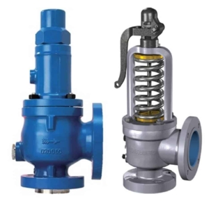
Relief valves
A relief valve is a gradual lift pressure relief device actuated by inlet static pressure. An opening is proportional to the increase in inlet pressure over the opening pressure of the valve.
It may be provided with an open or enclosed spring housing that also known as a bonnet. Here in the image, you can see the open spring type bonnet. The opening pressure at which valve act, can be adjusted by changing the load on spring.
Here in the image, you can see the enclosed spring type Relief valves for closed discharged applications. Relief valves are commonly used with non-compressible liquid systems in chemical, petrochemical, and oil & gas industries.
Safety valves
A safety valve is a rapid opening or pop-up action pressure relief valve actuated by inlet static pressure. Safety valves are used primarily with compressible gasses. Particularly for steam and air services.
Safety valves are classified according to the lift of the disk and bore of the valve. Types of safety valves are low lift, full-lift, and full-bore safety valves.
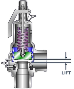
- In a low-lift safety valve, the disk lifts automatically such that the actual discharge area is determined by the position of the disk.
- While in case of a full lift safety valve, the disks lift automatically such that the actual discharge area is not determined by the position of the disk.
- The full-bore safety valve has no protrusions in the bore that can restrict or work as a controlling orifice to reduce the flow from the valve.
Safety Relief Valves
- Safety Relief Valves has a combined characteristic of the Safety valve & Relief valve. It performs as a safety valve, open by pop-up action when used in a compressible gas system and performs like a relief valve, opens in proportion to the overpressure when used in liquid systems
- Different types of Safety Relief Valves used in process piping
- These valves are classified as conventional type, pilot operated, balanced bellows type, power actuated, and temperature actuated type.
Pressure Relief Valve
The conventional pressure relief valve is characterized by a rapid pop action or by opening proportionally to the increase in pressure with respect to the opening pressure of the valve.
The main parts of the Conventional pressure relief valve are a body, bonnet, disk, disk holder, seat, and spring. Based on the seating material, conventional pressure relief valves are classified as metal seated valves and soft seated valves. See the image for clarity.
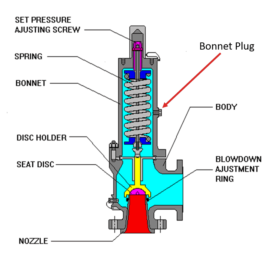
During normal operating conditions, the pressure at the inlet is below the set pressure, and the disk remains seated on the nozzle, preventing flow through the nozzle.
The working principle of a conventional spring-loaded pressure relief valve is based on the balance of force. That means the spring load will keep the disk on the seat till the system pressure is less than the spring force.
This pressure is known as set pressure. The disk remains seated on the seat in the closed position till the inlet pressure exceeds set pressure and overcome the spring force. When the inlet pressure is reduced to a level below the set pressure spring force close the valve.
Conventional pressure relief valves are used for applications where an excessive variable or built-up back pressure is not present. Back-pressure will directly affect the valve performance. A pressure built-up on the outlet side of PSV is known as backpressure. You will learn more about back pressure in the lecture on bellows type PSV.
Advantages of Conventional PRV
- It Can be used in all kind of Gas and Liquid services
- Suitable for high pressure and temperature services
- Low cost compares to other types
Disadvantages of Conventional PRV
- Backpressure can affect the functioning of the valve
- Spring is subjected to corrosion if service material is corrosive
- Not suitable for hazardous services
Vacuum Relief Valve
A simple vent can Provide protection against vacuum. Our home water storage tanks are fitted with this kind of simple vent. But in the industrial tank which stores various chemical and hydrocarbon, this simple vent may release vapor of these products in an atmosphere, which can be odorous, toxic, potentially hazardous. To avoid such release, a special vacuum relief valves are used.
Pressure Vacuum Relief Valve -PVRV
The pressure vacuum relief valve or pressure-vacuum vent, are designed to maintain a tight seal until system pressure or vacuum exceeds the set pressure of the valve. When overpressure occurs, the pressure lifts the disk just like a safety valve, allowing vapors to pass.
When a vacuum occurs, vacuum lifts the disk and lets the air inside to break the vacuum. It is like breathing of a tank. This PVRV arrangement prevents continuous vapor loss to the atmosphere as it opens only when the set pressure is reached. You can see the image for a better understanding.
P&ID Symbol Legend
Posted by Daniel Belisario | 12/23/2020
Piping and Instrumentation Diagram Symbols Detailed Documentation provides a rich set of shapes & symbols for documenting P&ID and PFD, including shapes for the instrument, valves, pump, heating exchanges, mixers, crushers, vessels, compressors, filters, motors, and connecting shapes.
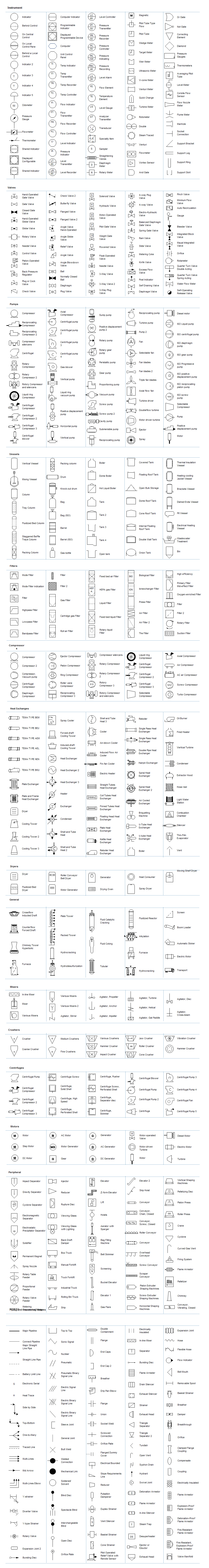
P&ID Symbols and Their Usage
In a P&ID, different types of shapes are used to represent various equipment, valves, instruments, and pipelines, which are called P&ID symbols.
A piping and instrumentation diagram is more complicated than a process flow diagram. Edraw includes more than 2000 vector P&ID symbols used to depict mechanical equipment, piping, piping components, valves, equipment drivers, instrumentations, and controls. Get the most comprehensive collection of P&ID symbols from our pre-defined library.
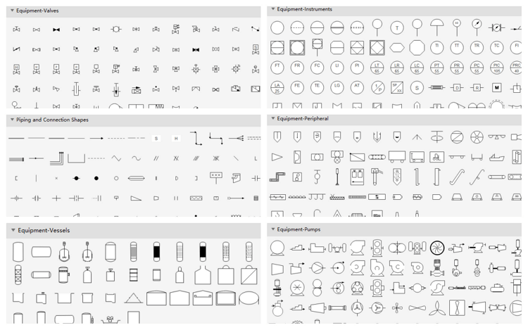
Part 1: P&ID Equipment Symbols
Pumps and tanks come in a variety of designs and shapes. You have both abstract symbols and simulation images to choose from. Learn the basic knowledge about the piping and instrumentation diagrams.
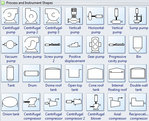
Pump is a mechanical device using suction or pressure to raise or move liquids, compress gases, or force air into inflatable objects such as tires. The symbols for pumps may closely resemble those for compressors.
Centrifugal pump is a rotodynamic pump that uses a revolving impeller to add to the force and pressure of fluids.
Gear pump provides continuous, non-pulsing flow making it ideal in chemical installations.
Sump pump is widely used to remove accumulated water from a sump pit or other location.
Vacuum pump is applied to improve the efficiency of steam heating systems in many ways. The most important consideration is the rapid and efficient removal.
Screw pump is the Archimedes screw pump that is still used in irrigation and agricultural applications.
Tank is for storing process fluids of various types under different process conditions.
Onion tank refers to an open-top collapsible bladder designed for use as a mobile storage solution when recovering contaminants.
Compressor is a mechanical device that takes in a medium and compresses it to a smaller volume. A mechanical or electrical drive is typically connected to a pump that is used to compress the medium.
Axial compressor is widely used in gas turbines, such as jet engines, high-speed ship engines and small scale power stations.
Reciprocation compressor is typically used where high compression ratios are required per stage without high flow rates, and the process fluid is relatively dry.
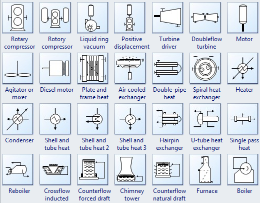
Rotary compressor is a type of gas compressor which uses a rotary type positive displacement mechanism.
Mixing is a device that combine or put some materials together to form one substance or mass.
Mixing vessel is a container that is used to blend several components together.
Heat exchanger is a device used to transfer heat energy between two process flows. Heat exchangers transfer heat energy through conductive and convective heat transfer.
Cooling towers transfer heat energy to the outside air through the principle of evaporation.
Cooler is a device, container or room that cools air through the evaporation of water or keeps air cool.
Turbine driver is used to drive pumps and fans at petrochemical plants.
Furnace is a device for heating a continuous current of air by means of a fire contained within the apparatus and without mingling the fresh air with the products of combustion.
Boiler is a closed vessel in which water or other fluid is heated.
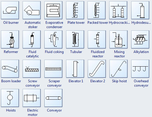
Oil burner is engineered from the ground up exclusively to burn waste oils.
Automatic stoker is applied to supply hot water to central heating systems.
Plate tower is used extensively in many processes and industrial applications.
Packed tower is a type of packed bed used to perform separation processes.
Elevator is used to control the position of the nose of the aircraft and the angle of attack of the wing.
Mixing reactor is widely used in the chemical industry to promote mixing.
Part 2: P&ID Valves Symbols
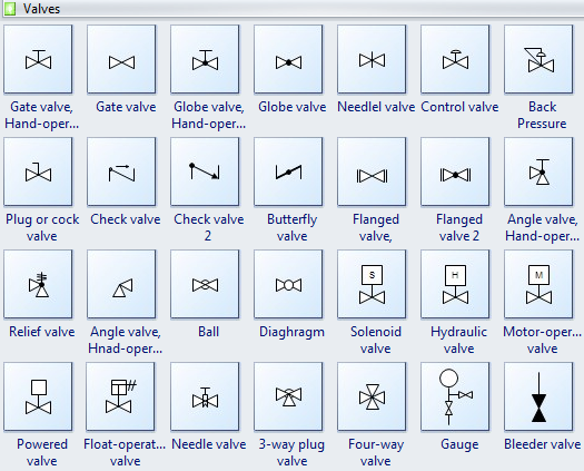
Gate valve is a device used to control the flow of liquids and gases.
Check valve, also known as a one-way valve, is to prevent the line of medium back.
Globe valve is a mechanism used to control or stop the liquid or gas flow through a pipe.
Ball valve is a valve with a spherical disc, the part of the valve which controls the flow through it.
Butterfly valve is installed between two flanges using a separate set of bolts for each flange.
Angle valve is oriented at an angle of 90 deg of gate valve.
Part 3: P&ID Piping Lines Symbols
Process flow diagrams use special piping lines to represent how signals are transmitted between equipment. These symbols are used to identify how the instruments in the process connect to each other. And what type of signal is being used. (electrical, pneumatic, data, etc.)
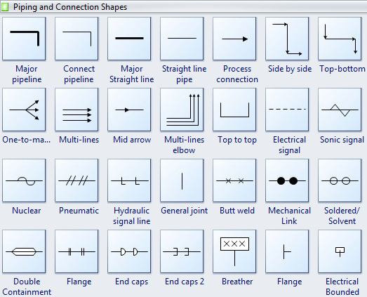
Major pipeline is used to connect the equipment in any position.
Major straight line is used to connect the equipment in the same horizontal or vertical position.
Process connection help to create the process flow between equipment. (Double click process connection to edit the description)
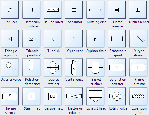
Part 4: P&ID Instruments Symbols
Process Flow Diagram use symbols and circles to represent each instrument and how they are inter-connected in the process.
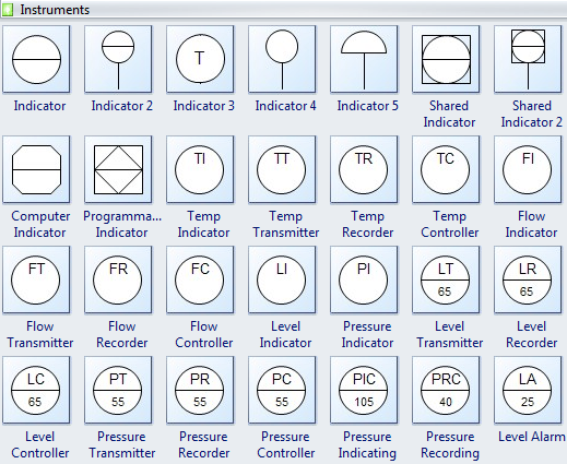
These instrumentation symbols can easily change in types by clicking the quick action button while designing.
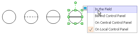
With large pre-drawn examples and more than 8500 symbols, drawing couldn’t be easier! Click here to learn more about Process and Instrument Diagram Symbols. (see below)
Learn how to create a piping and instrumentation diagram here (see below). You can also look at the video below and know how to make a P&ID with professional software in minutes!
Part 5: More P&ID Symbols – Simulation Images
P&ID Designer includes lots of lifelike images enabling presentation-quality diagrams. View manufacturing flow chart symbols. (see below)
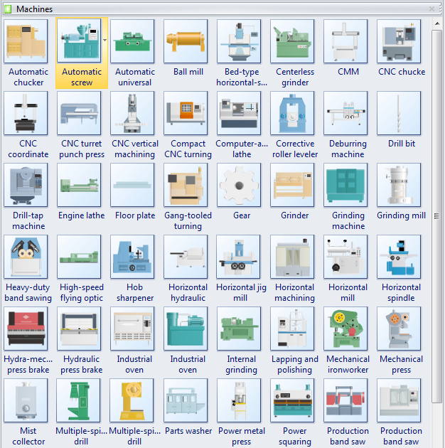
More Related (see below)
P&ID Software for Linux – Easy Piping and Instrumentation Diagram Program
Working with PIDs & PFDs Component Data
Process and Instrument Diagram Symbols
Posted by James Freeman | 12/03/2019 Pre-drawn process and instrument diagram symbols like centrifugal pump, vertical pump, screw pump, bin and more help create accurate diagrams and documentation.
Edraw process and instrumentation templates include lots of process and instrumentation shapes, centrifugal pump, vertical pump, horizontal pump, vertical pump, sump pump, vacuum pump, screw pump, positive displacement pump, etc. These shapes will facilitate the improvement of your drawing level.
Process Flow Diagram Symbols – Process and Instrumentation Shapes
Process and Instrument Diagram Shapes
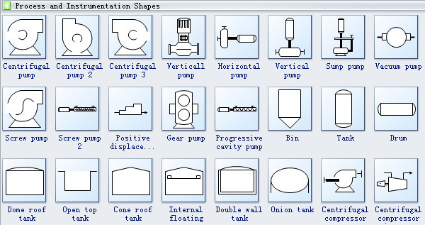
Centrifugal pumps are used to transport fluids to the hydrodynamic energy of the fluid flow. Centrifugal pump converts the input power to kinetic energy in the liquid by accelerating the liquid by an impeller.
Sump pump is a pump used to remove water that has accumulated in a water collecting sump basin, commonly found in the basement of homes. Sump pumps help keep your basement or crawlspace dry.
Vacuum pump is a device that removes gas molecules from a sealed volume in order to leave behind a partial vacuum
Screw pump is a positive displacement pump that use one or several screws to move fluids or solids along the screw axis.
Gear pump uses the meshing of gears to pump fluid by displacement.
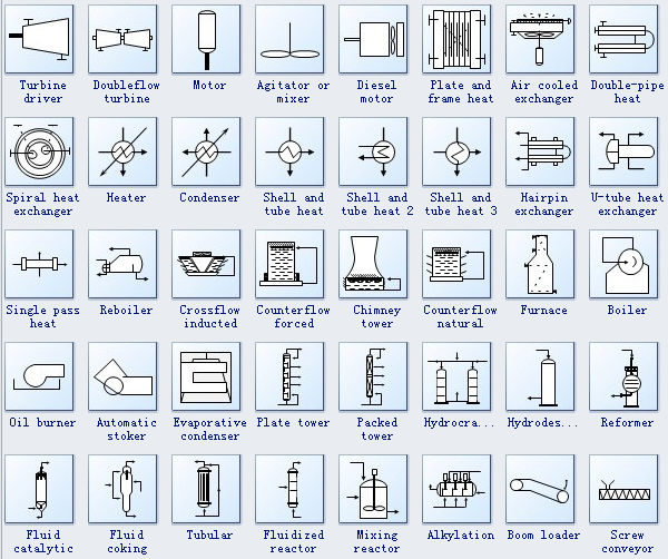
Motor is a device that creates motion. It usually refers to an engine of some kind.
Heater is an object that emits heat or causes another body to achieve a higher temperature.
Condenser is a device for reducing a gas or vapor to a liquid.
Furnace is a device used for heating. The name derives from Latin fornax, oven.
Boiler is a closed vessel in which water or other fluid is heated. The fluid does not necessarily boil.
Oil burner is a heating device which burns fuel oil. The oil is atomized into a fine spray usually by forcing it under pressure through a nozzle
Tubular refers to the form of a cylinder or tube.
Process Flow Diagram Symbols – Piping and Connection Shapes
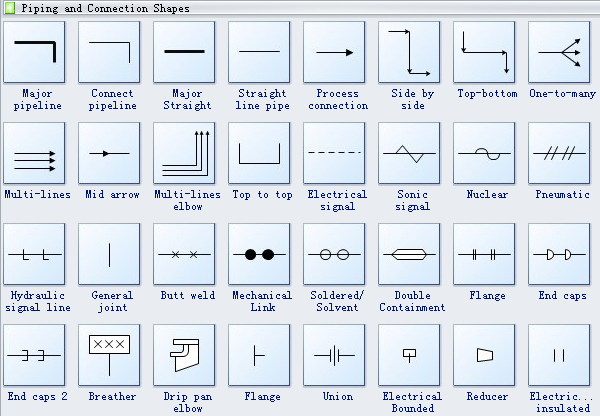
Flange is a projecting flat rim, collar, or rib on an object, serving for strengthening or attachment or (on a wheel) for maintaining position on a rail.
Reducer is the component in a pipeline that reduces the pipe size from a larger to a smaller bore (inner diameter).
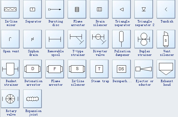
Separator refers to a mechanical device to separate fluids and solids.
Steam trap is a device used to discharge condensate and non condensable gases with a negligible consumption or loss of live steam.
Need fresh looking process and instrument diagram symbols for your design? These process and instrument diagram symbols are a cinch to pop in. And their crisp, fine detail will make spectacular, easy-to-understand diagrams and presentations to your customers.
How to Create a Process and Instrumentation Diagram (see below)
More symbols:
Basic Organizational Chart Symbols
Create a Piping and Instrumentation Diagram
Posted by James Freeman | 04/22/2020 The piping and instrumentation diagram is often a vital and basic part of a whole project, which requires excellent tool for creating. Edraw helps engineers create creative process and instrumentation diagrams to save time and improve accuracy.
What’s a Piping and Instrumentation Diagram?
Piping and Instrumentation Diagram (P&ID) (see below), which is also known as process and instrumentation diagram, is a schematic illustration in the process industry showing the piping of the process flow together with the installed equipment and instrumentation through graphical symbols. It shows how industrial process equipment is interconnected by a system of pipelines, which is required by engineers to start planning for the construction of a plant. Learn P&ID diagram knowledge. (see below)
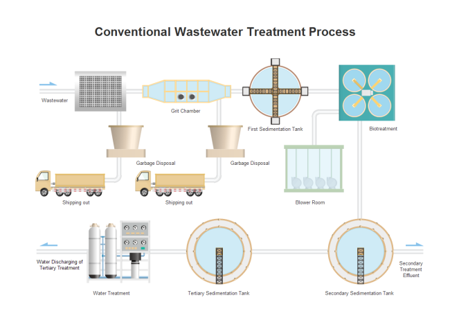
Why Piping and Instrumentation Diagram is Important?
1. It’s used as a Process Plant Layout and Piping Design reference for checking engineering and design documents and drawings associated with a project.
2. It plays a very important role in plant maintenance and modification in that they demonstrate the physical sequence of equipment and system as well as how they all connect.
3. It’s the last stage of process design and serves as a guide for those who will be responsible for the final design and construction.
4. It’s also used to train operators and plant simulators.
How to Create a Piping and Instrumentation Diagram?
Start with Pre-designed Templates
In Edraw, the P&ID Template helps you easily create piping and instrumentation diagrams using massive built-in symbols. Double click the template from Engineering Category on the starting page to enter the drawing page. You will discover abundant symbols and easy-to-use tools available for piping and instrumentation diagrams.
Create P&ID with Standard Built-in Symbols
Edraw includes more than 500 vector P&ID symbols created from different international standards. In Edraw library, all P&ID symbols are classified as equipment, valves, piping lines, instruments, etc., which you can easily use to depict mechanical equipment, piping, piping components, valves, equipment drivers and instrumentation and controls. Go to Process and Instrumentation Symbols and Their Usage (see above) page to have a general knowledge about the symbols.
Basic Steps to Create P&ID:
1. On the File menu, point to New, point to Engineering, and double click Process and Instrumentation template. A new drawing page will open.
2. Go to the library pane on the left of the canvas. From Equipment, drag equipment shape onto the canvas.
3. Use pipelines to connect the equipments.
- Drag a pipeline from the Connection Shape onto the drawing page. Position an endpoint with an equipment shape. Connection points (blue x) will appear on the equipment shape. You can connect with any connection point as you want. When the endpoint turns red, it means it’s glued to the equipment shape. Note: Connection point can be created through Connection Point Tool under Home tab if you need.
- Drag the other endpoint to another equipment shape as above.
- Pipeline style is changeable if you need a special line weight or arrow direction. Go to Home tab Line button to set the pipeline style.
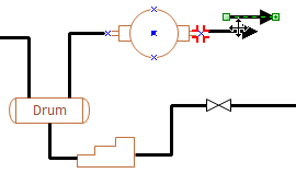
4. You can add valves and instruments in the same way.
5. Rotate a shape through the rotation handle when it’s selected.
6. Reposition a shape by dragging it to the required place.
7. Add data to a component by double clicking on it. p>
Print: When a piping instrumentation diagram is done, it’s easy to print and share with more people. On the file menu, point to Print to set for print options. You can change settings with fewer clicks and see the print preview in real time.
Export: Edraw offers support for exporting your diagram to various formats, including Microsoft Office, PDF, and many other graphic formats. On the File menu, point to Export & Send for Export options.
More Features Making Edraw the Best Choice:
- Edraw has built in a set of nice looking themes with advanced effects. It’s easy to change the whole diagram by changing the active theme with just a few clicks. You don’t have to be professional in designing.
- All Edraw documents are vector graphic files with high clarity.
- Smart tools are provided for automatic formatting. Easily arrange, rotate, group and align objects.
- Edraw offers various customization options, using which you can adjust line width, color, style, font size and style, text color, and much more.
- Easy to add photos, images and edit text fields.
Here is a complete example of piping and instrumentation diagram created by Edraw.
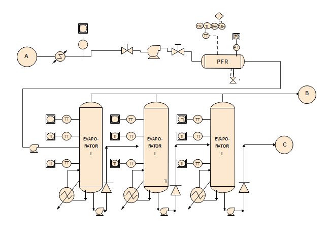
More Related
How to Create Process Flow Diagram
Basic Knowledge About Piping and Instrumentation Diagram
Piping and Instrumentation Diagram Symbols
Manufacturing Flow Chart Symbols
osted by James Freeman | 11/26/2020 Manufacturing flow chart symbols is ideal for manufacturing, industrial, and production engineers, manufacturing and operations managers, management consultants in manufacturing management and engineering.
Manufacturing Shapes
The manufacturing flow chart is the best method for documenting manufacturing operations and their sequence. A detail manufacturing flow chart should be developed for each major manufacturing area. It includes not only the operations themselves, but every transport between operations, every predictable delay, inspections, and storage.
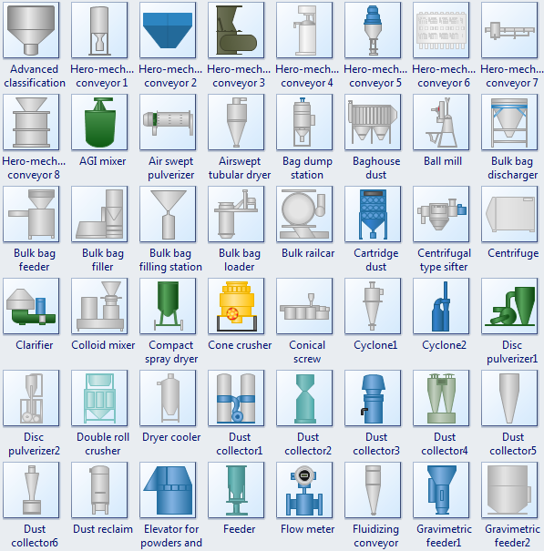
Process Flow Symbols
In the Manufacturing flowchart, the following process flow symbols represent different items in a process or operation.
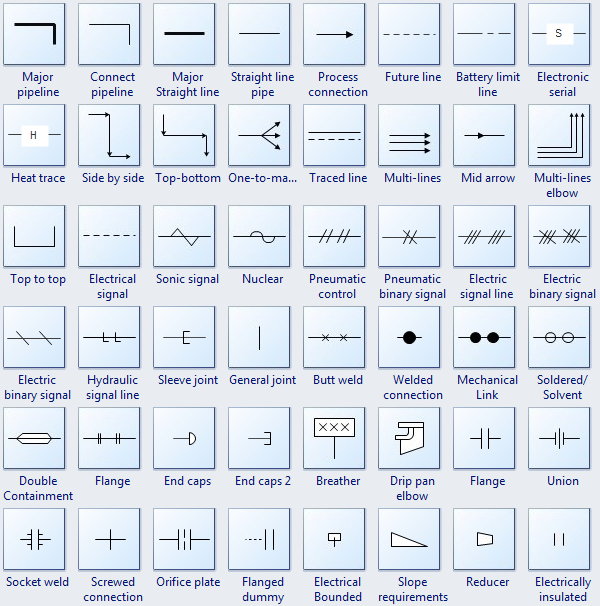
Valves in Manufacturing Flow Chart
A manufacturing flow chart is a pictorial representation of a process, using a variety of symbols connected by lines and arrows. There are lots of valves symbols available for the all major process controls.
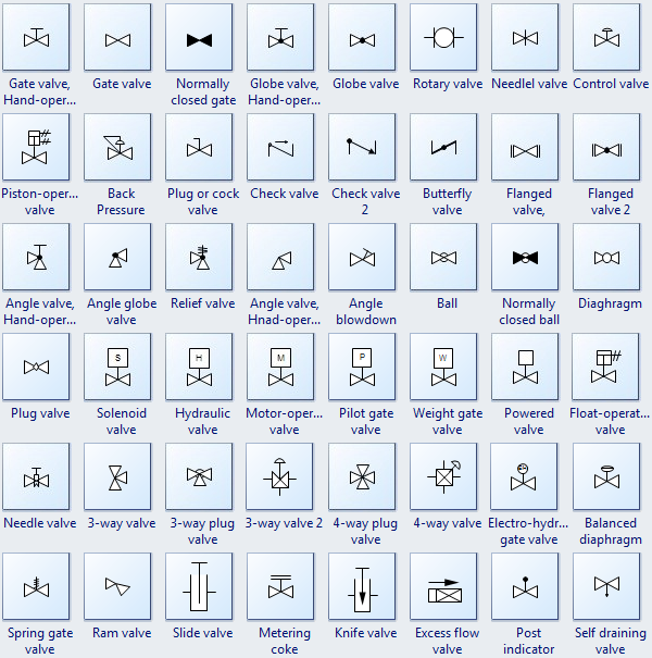
Indicators in Manufacturing Flow Chart
Although not a substitute for a manufacturing flow chart, the different indicators can be useful for the collection of much pertinent information.
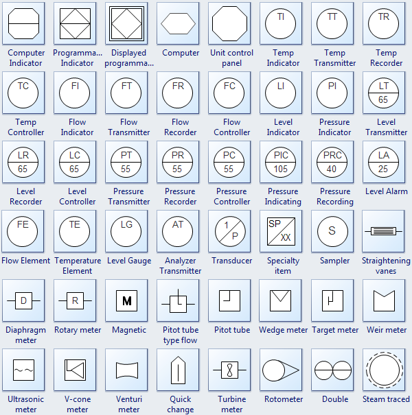
All the symbols above can be found in Edraw diagram software, download it now to see it’s powerful abilities to design flowchart for industry and engineering.
More Shapes
Layout of P&ID
Posted by Janice | 04/22/2020 Requirements of the layout of a P&ID are intended to gain a balance between the desire to present all necessary data on P&IDs and the need to make PIDs easy to read and understand.
In terms of layout, a P&ID should follow the criteria below.
1. Reading order: Criteria contained herein apply to reading a P&ID from the bottom or right side of the drawing.
2. Drawing size: standard size is 22″ x 34″ (560 mm x 864 mm).
3. Present each P&ID to avoid disorder and allow future modifications. Show no more than three pieces of major equipment per P&ID. Leave more space for text entry and easier reading.
4. Show primary flow on each P&ID from left to right. Show flow through equipment relative to actual arrangement (e.g., cooling water supply in bottom of exchanger tube bundle and cooling water return out top).
5. Line weight variety: Make primary process lines heavier than secondary and utility lines to show hierarchy. Change line weight with Line tool in Home tab.
6. Show off-page connector arrows for primary, secondary and instrumentation lines entering the P&ID horizontally 0.25″ (6.4 mm) from the left inside borderline and exiting 0.25″(6.4 mm) horizontally from the right inside borderline. Utility connectors may be shown at any convenient location within diagram area.
7. Show the center point of a PSE (Pressure Safety Element) identification bubble 0.5″ (12.7 mm) above a horizontal line or left of a vertical line and 0.5″ (12.7 mm) away from the rupture disc or equipment.
Here is a complete example of piping and instrumentation diagram created by Edraw.

More Related
How to Create Process Flow Diagram
Basic Knowledge About Piping and Instrumentation Diagram
Piping and Instrumentation Diagram Symbols
Acronyms Used in P&ID
Posted by Janice | 11/23/2020 Some commonly used acronyms in P&ID are listed here for reference.
Acronyms of Equipment
AHU — AIR HANDLING UNIT
ASV– AIR SWITCH VALVE
CA — AIR COMPRESSOR
CAE — COOLER, AIR EVAPORATIVE
D — DAMPER
ADA — DESICCANT AIR DRYER
DAMD — DUCT AIR MONITOR DEVICE
ES — EXHAUST STACK
FAB — FILTER AIR BOX
FANE — FAN EVALUATOR
FAR — FILTER AIR REPLACEABLE
FC — FAN CIRCULATING
FD — FIRE DAMPER
FE — FAN EXHAUST
FRA — FAN, RETURN AIR
FRL — FILTER AIR ROLL
FA — FAN SUPPLY
HEAP — HIGH EFFICIENCY PARTICULAR AIR FILTER
HX — HEAT EXCHANGER
Acronyms of Instrumentation Identification
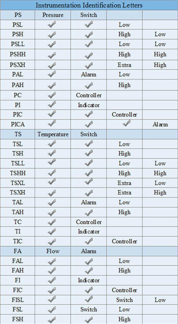
Acronyms of Minor Equipment
MT — MOISTURE TRAP
OIM — OPERATOR INTERFACE MODULE
SST — SYSTEM STATIC TOTALIZER
TCA — TANK COMPRESSED AIR
TK — TANK
T — TRAP
V — VALVE
VFD — VARIABLE FREQUENCY DRIVE/MOTOR CONTROLLER
AW — Acid waste
NW — Normal waste
OW — Oil waste
SW — Sanitary waste
FA — Flame arrester
ND — Non-radioactive drain
SPR — Separator
SR — Strainer
SRY — Y-type strainer
SRT — T-type strainer
SRB — Bucket type strainer
TS — Temporary strainer SIL – Silencer
SG — Slight glass
SC — Sample cooler
DF — Drain funnel
LM — Line mixer
RO — Restriction orifice
MO — Mixing orifice
RD — Rupture disk
EJ — Expansion joint
PID Examples
Air Conditioning PID Template
You can quickly draw P&IDs and PFDs by starting from ready-made templates which are for free download and immediate use. When modifications are needed, drag process engineering equipment shapes onto your drawing page, connecting them with ‘smart’ pipelines, and then dragging components, such as valves and instruments, onto the pipelines. Created by EdrawMax, this templates is available in different formats.
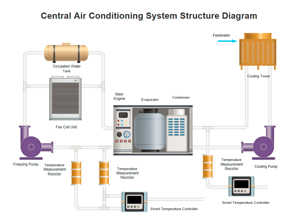
Thermal System PID Template
Edraw includes PID examples like this template that you can easily edit and customize in minutes. It is available in different formats, clearly showing the main process of multi-energy complementary instant thermal system.

Power Generation Heating PID Template
The power generation heating P&ID template is FREE for you to download and use for personal, business and educational purposes. Try to edit it simply by clicking the action buttons or dragging predefined symbols.
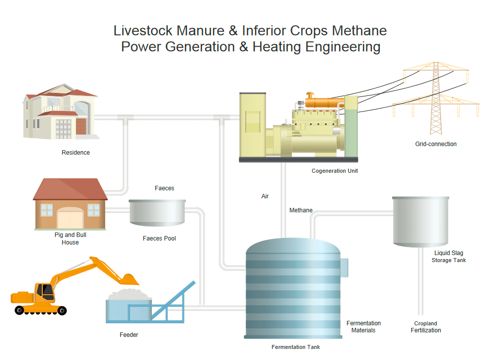
Others are reading:
Basic Knowledge about Piping and Instrumentation Diagram
How to Create a Piping and Instrumentation Diagram
What is a Piping and Instrumentation Diagram (P&ID)
Posted by Daniel Belisario | 04/22/2020 Piping and instrumentation diagram (P&ID) is not difficult to understand by reading this simple P&ID article with basic concepts and key aspects.
Contents
- What is a P&ID?
- P&ID Elements?
- P&ID Key Usages
- P&ID Symbol Legend
- P&ID Examples
- More Free P&ID Templates
- How to Create a P&ID Conveniently?
What is a Piping and Instrumentation Diagram (P&ID)?
A piping and instrumentation diagram displays the piping components (for example equipment, valves, reducers and so on) of an actual physical process flow and is often used in the engineering projects, such as setting up steam boilers, heat exchangers, electric boilers and more. To read a piping and instrumentation diagram, simply break down the overall diagram into smaller parts and then trace from a single equipment and follow the pipeline. Piping and instrumentation diagram also has a close relationship with the Process Flow Diagram (PFD). The latter type shows a picture of the separate steps of a process in sequential order.
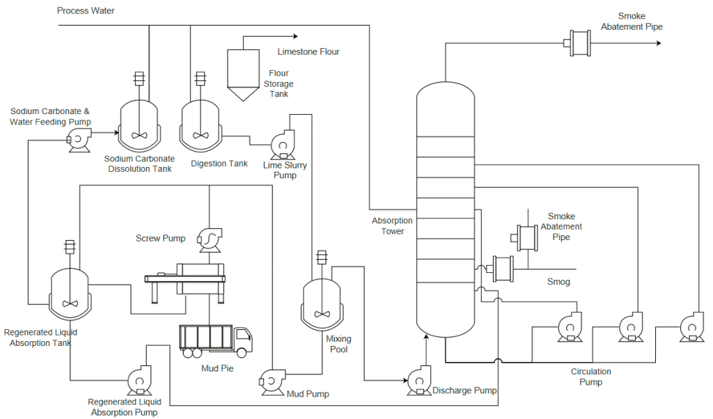
Main Purpose of using piping and instrumentation diagrams are:
- To better understand the design conditions of an engineering project;
- To operate, maintain and modify the process system efficiently;
- To conveniently layout out and demonstrate the physical sequence of systems with the focus on the control and shutdown schemes, safety and regulatory requirements, and the basic start-up and operational details.
Piping and Instrumentation Diagram Elements
There is no standard form for a piping and instrumentation diagram, but you may see some of the following elements:
- Different kinds of equipment including drain, reducers, drains and so on;
- Equipment details such as sizes, tag numbers, rating, capacity and more;
- Details about the overall diagram including element identification, insulation requirement, flow directions, interconnections reference, quality level, various interfaces, permanent start-up and flush lines;
- Symbols including valves;
Piping and Instrumentation Diagram Usages
Piping and instrumentation diagrams have been used in many fields such as metallurgical sector, air conditioning industry, power generator sectors and so on. The key usages of such diagrams are:
- For designing a manufacturing process for a physical plant with complex chemical or mechanical steps. This is especially important for a safety check.
- For training new workers and contractors before they start work in the plant.
- To derive project capital cost estimate and develop project contract specification, for example, the guidelines and standards for facility operations.
P&ID Symbol Legend
The piping and instrumentation diagram symbols, which show the functional relationship between piping, instrumentation, and system equipment units, are very important for users to understand the subject. Unlike floor plan symbols that are dimensionally accurate, piping and instrumentation diagram symbols are mainly used to illustrate the process of a system. All piping and instrumentation diagram symbols can be divided into seven main categories: equipment, piping, vessels, heat exchangers, pumps, instruments and valves.
Equipment
Equipment has unique miscellaneous units that are different from the other piping and instrumentation diagram categories. The equipment category contains facilities and devices such as compressors, conveyors, motors, turbines, vacuums, and more.
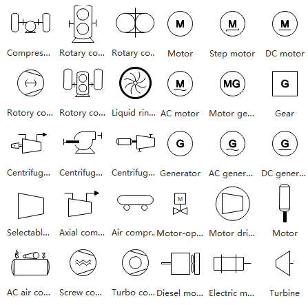
Piping and Connection Shapes
Pipes are used to transport fluid substances in industrial diagramming. Piping has a number of different materials, such as metal and plastic, to be used to create various types including multi-line pipes, separators, and so on.
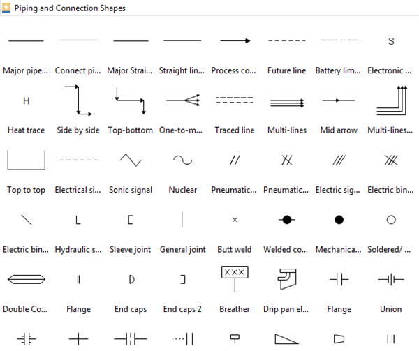
Vessels
Normally, a vessel is a kind of container that is used to store fluid, or change the features of the fluid during storage. The vessels category covers from tanks to columns as you can see below:
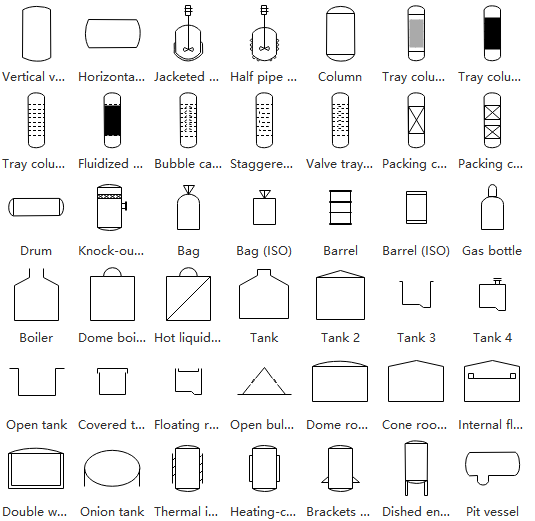
Heat Exchangers
A heat exchanger is used to efficiently transfer heat from various kinds of areas or mediums. This category includes many different forms of devices such as boilers, condensers, hose reel and more.
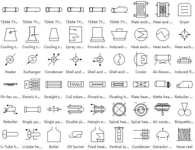
Pumps
Generally, a pump is a kind of device that uses pressure to raise or compress fluids in and out of other industrial facilities. This category covers pumps, fans, ejector, spray and many more.
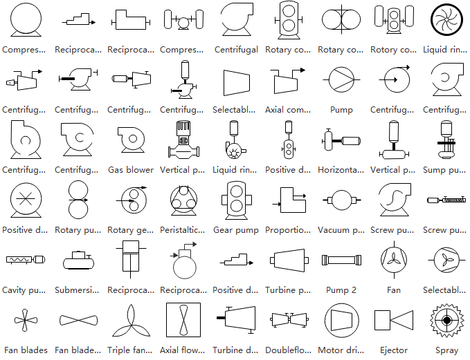
Instruments
An instrument is used to measure and control quantities including flow, temperature, or pressure. The instruments category includes houses indicators, transmitters, weir meter, controllers and so on.
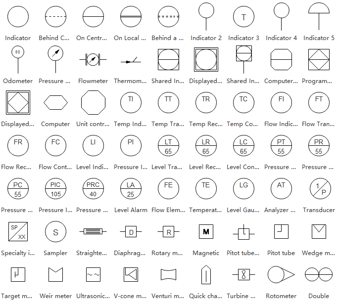
Valves
A valve is used by engineers to control the flow of a fluid by opening or closing passageways in a piping system. This section includes rotameters, gauge, ball and more.
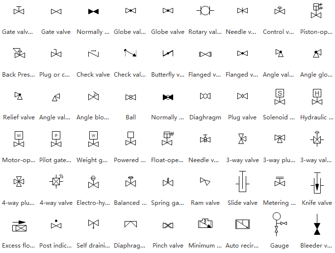
P&ID Examples
Using examples with colored labels helps a lot to understand the piping and instrumentation diagram. Simply check out the following examples from different industrial fields. Feel free to click on any of these examples to see more.
Water Boiling Process
This example here shows a general process for changing from the liquid phase to a gaseous phase. In this case, the vapor pressure of the liquid has the same level of the atmospheric pressure exerted on the liquid.
(Water Boiling Process PID Template: A P&ID template for water boiling process is provided here. You can use the template to learn this knowledge or download for your own P&ID design. Hundreds of P&ID examples are provided in our piping design software.)
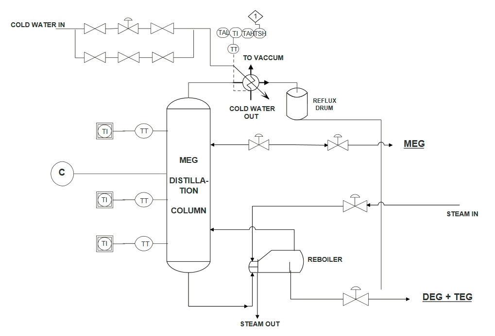
Power Generation System
A power generation system, which is also called as a power plant or power generation station, is a set of industrial equipment for generating electric power. You can see different types of facilities such as power supply tanks and LP turbines in the following diagram.
(Power Generation PID Template: This free customizable power generation P&ID template has been developed to help you when planning a presentation, document archive or workflow analysis. Make some modifications to suit your need. This can be easily handled with the smart action buttons.)
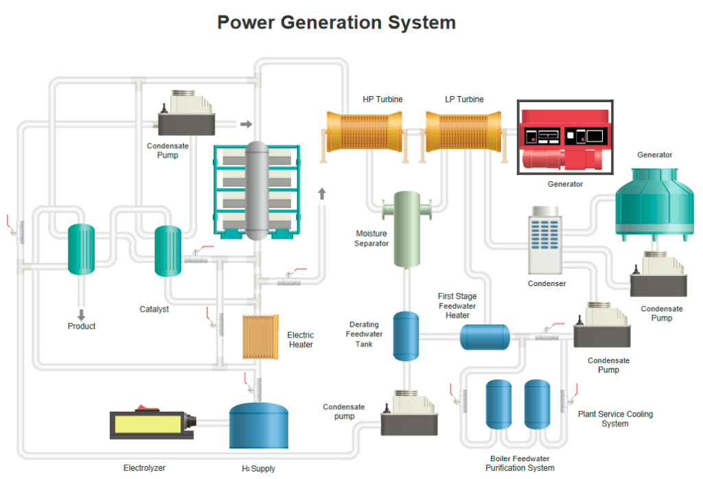
Evaporate Piping and Instrumentation Diagram Example
This diagram here shows an evaporator system with a number of elements and three key evaporators. By following the pipelines in this diagram you can clearly see how water is evaporated.
(Evaporate Process PID Template: The evaporate process P&ID template shows the evaporator system and how water is evaporated in the system. You can use it as a starting template when designing your own evaporator process and instrumentation diagram.)
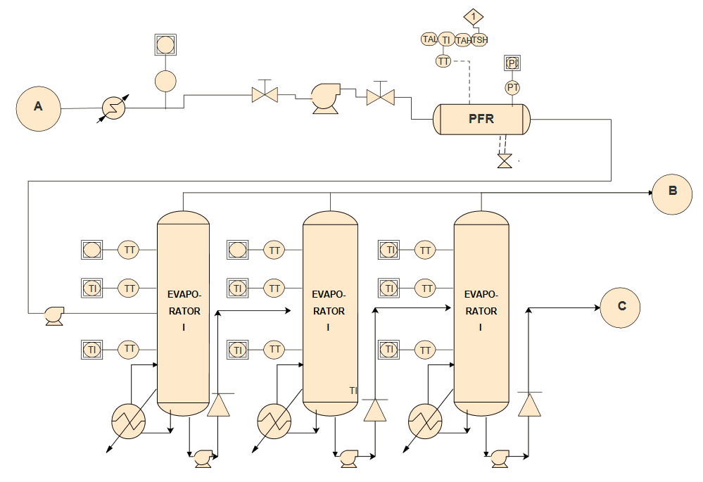
Air Conditioning System
This piping and instrumentation diagram example here shows the general process of removing heat and moisture from a certain space in order to improve the living environment. The key air conditioner is set at the middle and equipped by a series of pipelines in different directions.
(Air Conditioning PID Template: You can quickly draw P&IDs and PFDs by starting from ready-made templates which are for free download and immediate use. When modifications are needed, drag process engineering equipment shapes onto your drawing page, connecting them with ‘smart’ pipelines, and then dragging components, such as valves and instruments, onto the pipelines. Created by EdrawMax, this templates is available in different formats.)
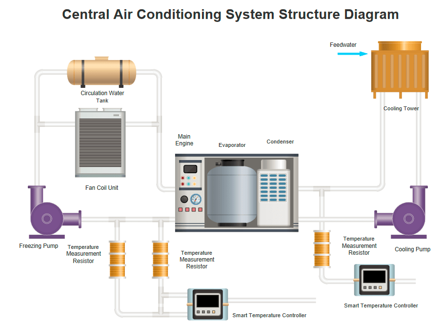
Low Dust SCR System
SCR refers to the Selective Catalytic Reduction, which is an advanced emissions control system. Hit on the diagram below to check out more details, or you can free download it in PDF format
(Low Dust SCR System Template: This low dust SCR system PFD template is a diagram that instantly brings you back to being on purpose. The process flow diagram is available for viewing in both PFD and editable formats. Download it to make it your own or share it with others.)
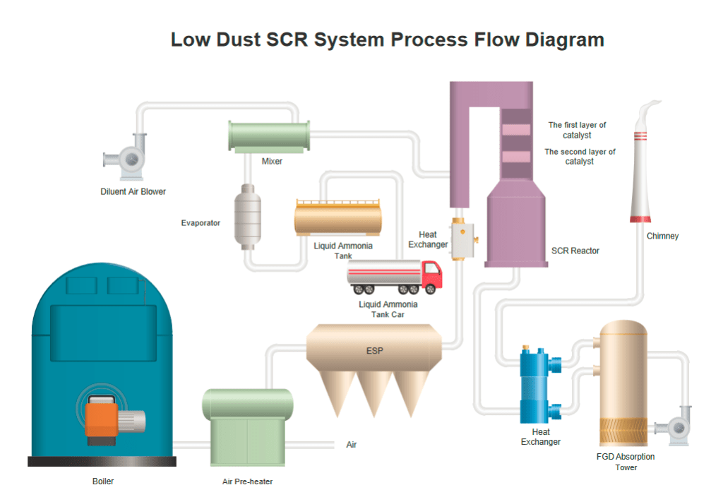
How to create a P&ID Conveniently?
How to create a P&ID Conveniently?
Generally, there are 4 steps to do so:
Step 1: Add Shapes
Drag and drop built-in standard editable symbols in the library. Alternatively, you can use a preset template to faster your work.
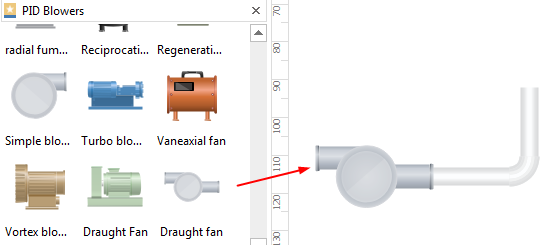
Step 2: Connect Shapes
Connect piping and instrumentation diagram shapes and equipment with pipelines in different directions. Adjust the length and width of a pipeline according to your specific needs. Also, keep in mind that some equipment may require special configuration.
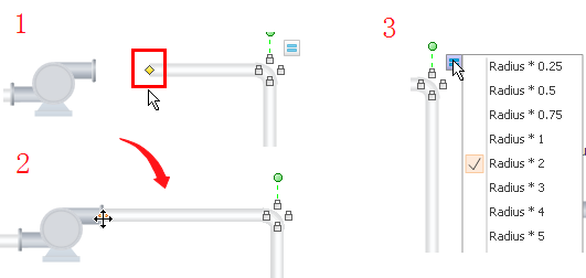
Step 3: Customize Elements
Customize your piping and instrumentation shapes by changing the default color and size. You can further add text to or label each of the equipment.
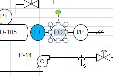
Step 4: Save, Print and Export
Export to different formats including PDF, SVG, Visio, Graphics etc. You can also save files on built-in personal or team cloud for better communications.
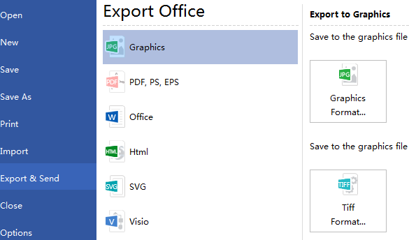
Why Choose Edraw Max for Creating Piping and Instrumentation Diagrams?
Compared to many other diagramming tools in the market, Edraw Max can make your work more efficient based on easy-to-use features. Enjoy the abundant editable shapes and template with the drag-and-drop editor. You can also auto-connect, label, or font your shapes quickly thanks to Edraw Max’s great usability and flexibility. Once finished your work, easily export to many different formats including PDF, SVG and Visio to share with your colleagues. Explore more advanced functions by clicking on the free download button at the end of this page right now!
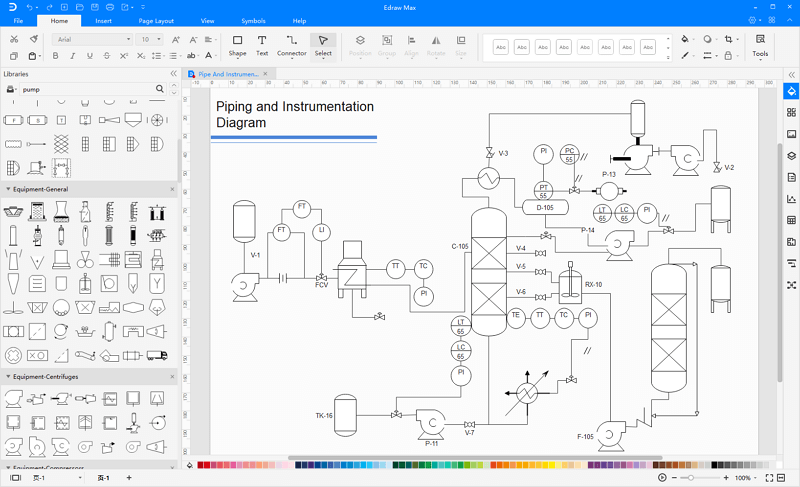
Read More
Video Tutorial – How to Create a P&ID
How to Create Professional-Looking P&ID
Posted by Janice | 11/18/2019 Create P&ID with an easy and highly efficient tool. Here teaches you how to make a professional P&ID step by step – including how to get the P&ID symbols and how to start drawing.
Knowing P&ID Before Start
What is P&ID?
P&ID, short for piping and instrumentation diagram, is a process documentation using graphical symbols, such as the service lines, instruments and controls, valves, and equipment. It is often used to by engineers and technicians to better understand the process and how the instrumentations are connected.
Who uses P&ID?
- Piping Designers
- Instrument Engineers
- Process Engineers
- Electrical Engineers
- Mechanical Engineers
What does a P&ID Used For?
- It shows the inner relationship of how each instrument is connected.
- It shows the relative location of equipment, actuators, and instruments in a process.
- It depicts a conceptual outline of a plant and its control architecture.
- It provides a common language for documenting, discussing, and analyzing a plant.
How to Create P&ID
Here shows simple guidelines on how to make P&ID with Edraw:
1. Start a P&ID Drawing Page
a. Use Lifelike Symbols
Start Edraw, from Available Templates, choose Industrial Automation. The templates window on the right will appear five P&ID drawing templates. Choose one based on your own purpose, and double click to open.
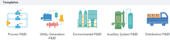
a. Use Standard Symbols
From Available Templates, choose Engineering. From the templates window on the right, choose Process Flow Diagram or Piping and Instrumentation Diagram.
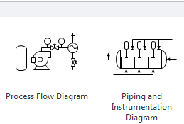
2. Add Symbols with Proper Annotation
When a drawing page is open, the corresponding symbol library will also open automatically on the left of the canvas. For example, if you open a Utility-Generation P&ID, you will see the libraries of ductwork, blowers, boilers, chemistry, containers, heaters, HVAC, logistics, machines, mixers, motors, powers, pumps and tanks. You can close the libraries you don’t need; or open other P&ID libraries.
Drag a symbol you need and place it on the canvas. All symbols are in vector format, which means you can change the colors freely or zoom in to a bigger size without any clarity loss.
To add an annotation, go to Home tab, click Text button and drag a text box to type the description.
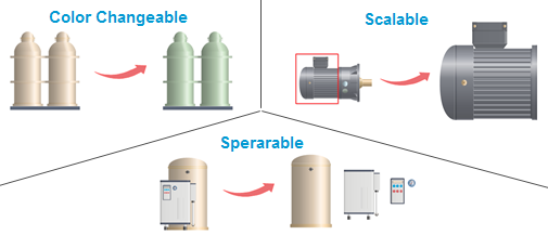
Tutorial – Learn how to create P&ID
3. Conneting P&ID
a. Use Lifelike Symbols
From the Ductwork library, drag a ductwork symbol with the correct direction. Drag the yellow handle to lengthen the pipe. Use floating button to set the pipe radius.
b. Use Standard Symbols
- Drag a pipeline from the Connection Shape library. Position an endpoint with an equipment shape. Connection points (blue x) will appear on the equipment shape. You can connect with any connection point as you want. When the endpoint turns red, it means it’s glued to the equipment shape. Note: Connection point can be created through Connection Point Tool under Home tab if you need.
- Drag the other endpoint to another equipment shape to connect two shapes.
- Pipeline style is changeable if you need a special line weight or arrow direction. Go to Home tab Line button to set the pipeline style.
4. Save and Export the P&ID
After it’s done, you can right click on your mouse and choose « fit to drawing », which can make the page size perfectly fit your drawing.
Since others may not have Edraw, you might need to export the document to other formats so that other people can open. Click File tab, and go to Export & Send. There are many formats available including PDF, Word, Html, Visio, PPT, BMP, EMF, PNG, JPG and much more.
Use Built-in P&ID Symbols for Making Professional P&ID
One of the features that makes Edraw an outstanding P&ID designer is its vast collection of symbols. This following picture shows only the tip of iceberg.
Symbol Categories:
| Ductwork Valves Pumps Motors Mixers Buildings | Chemistry Process Heating Process Cooling Wastewater Treatment Food Processing Lights | Tanks HAVC Logistics Safety Blowers Boilers |
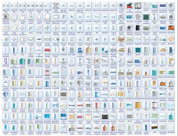
More Materials:
Basic Understanding of Piping and Instrumentation Diagram
Video Tutorial – How to Create a P&ID
FThis video shows you the basics on how to create a P&ID using Edraw.
How to Read Piping and Instrumentation Diagram
Posted by James Freeman | 04/22/2020 P&IDs, also known as Piping and Instrumentation Diagrams, or Process and Control Diagrams, are essential to many industrial operations. This page is a basic guide on how to read and understand Piping and Instrumentation Drawings (P&IDs).
In this article, we will explore the interpretation of Piping and Instrumentation Diagrams, or P&IDs. Being able to read P&IDs can benefit the process and management of a project a lot. Regardless of your experience or level of expertise, follow the instruction of this article, and you will find it rather easy to read a P&ID.
What is Piping and Instrumentation Diagram?
Piping and instrumentation diagram, also called P&ID, is a diagram used to show a graphical display of a complete system. It includes all piping, instruments, valves and equipment that the system consist of. Through a P&ID, you can get the following information:
- The mechanical and electrical details of a given system or process,
- Piping information such as sizes and material specifications,
- Continuation flags leading to the connecting P&ID’s,
- Flow arrows, DCS alarm types
- The connection types from the controllers to the field devices.
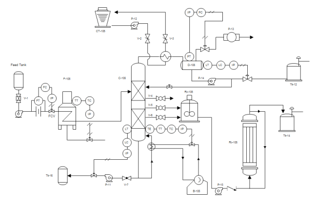
How to Read Piping and Instrumentation Diagrams
Here are a few aspects that you should pay attention to while reading a piping and instrumentation diagram. It is important for you to know what P&ID symbols means in a P&ID, and also tell how each symbol is constructed using graphical elements and connecting lines. If you manage to do this, it wouldn’t be difficult for you to read a piping and pnstrumentation diagram at all.
1. Identify and Understand Standard Equipment -Instruments
The first step to read a Piping and Instrumentation Diagram is to know how to read its symbols and shapes in the drawing. Edraw provides all kinds of symbols required in piping and instrumentation diagrams.
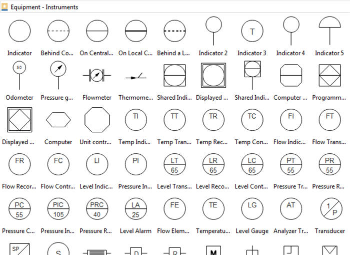
According to ISA S5.1, there are mainly 4 four graphical elements: shared control/display, computer, function, and programmable logic controller. This shapes represent both the physical or the software devices. In either case , it implies all the shapes needed in a piping and instrumentation diagram. You will see these shapes anytime a system is shown on the P&ID.
Discrete instruments:
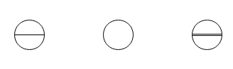
Shared control/display
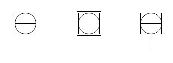
Computer function
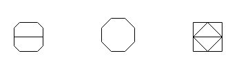
Programmable logic controller
Discrete instruments are indicated by circular elements. Shared control/display elements are circles surrounded by a square. Computer functions are indicted by a hexagon and programmable logic controller (PLC) functions are shown as a triangle inside a square.
2. Learn to Use Graphical Elements and Connecting Lines
The connections between elements is a way for engineers to identify a particular pipe in a standardized way. And different color indicates different pipes to avoide confusion. Adding a single horizontal bar across any of the four graphical elements indicates the function resides in the primary location category. A double line indicates an auxiliary location, devices located behind a panel-board in some other inaccessible location are shown with a dashed horizontal line.
3. Know the Letter and Number Combinations of a P&ID
Letter and number combinations appear inside each graphical element and letter combinations are defined by the ISA standard. Numbers are user assigned. The first letter defines the measured or initiating variables such as Analysis (A), Flow (F), Temperature (T), etc. with succeeding letters defining readout, passive, or output functions such as Indicator (I), Record (R), Transmit (T), and so forth.
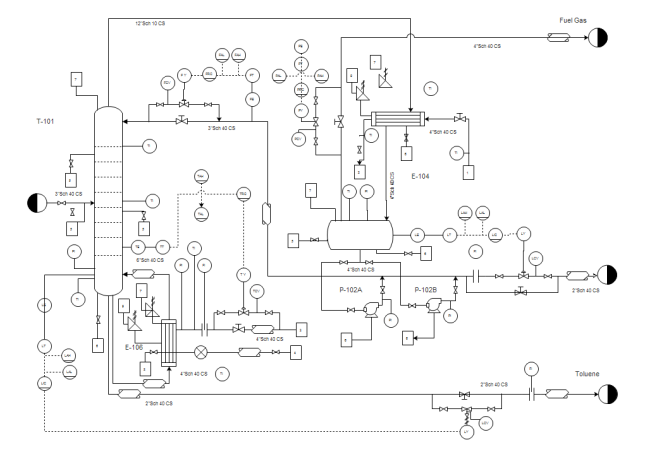
Piping and Instrumentation Diagram Example
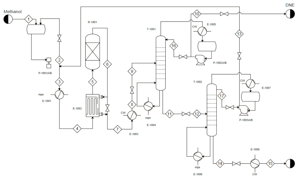
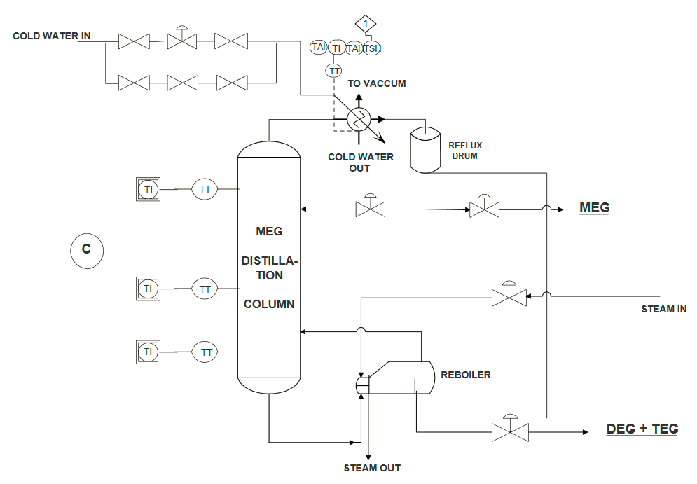

Related Articles
Edraw – Easy Piping Design Software
P&ID Wastewater Treatment Symbols and Their Usage
Posted by Janice | 01/06/2021 Pre-drawn wastewater treatment symbols represent water treatment, absorber, aeration basin, filter system, carbon absorber, chemical feeder, clean water system, elevated tank, etc. Vector symbols help develop accurate and presentation-quality diagrams and documentations.
From the P&ID wastewater treatment symbols library in Edraw, you can get the most comprehensive assembling of wastewater treatment symbols. They are precious resources greatly ease your work when creating piping and instrumentation diagram. This page shows a snapshot on how they look like and how to use them in diagrams.
Free Download P&ID Software and View All Examples
Wastewater Treatment Symbols
Part of the wastewater treatment symbols are presented below. We have tried to make them as inclusive as possible. There are water treatment, absorber, aeration basin, filter system, carbon absorber, chemical feeder, clean water system, elevated tank, incinerator, paddle dryer, micro screen, spigot, evaporator, grille, etc.
Water Treatment is the industrial-scale processes that makes water more acceptable for an end-use.
Absorber is a device which holds liquid for the absorption of refrigerant vapor or other vapors.
Aeration Basin is a holding and/or treatment pond provided with artificial aeration to promote the biological oxidation of wastewaters.
Clarifier is a device for filtering a liquid.
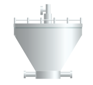
Chlorinator is an apparatus used in chlorinating.
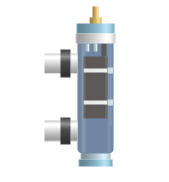
Digester is a vessel used to produce cellulose pulp from wood chips by cooking under pressure.

Incinerator is a waste treatment process that involves the combustion of organic substances contained in waste materials.
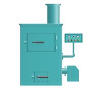
Evaporation is a type of vaporization of a liquid that occurs from the surface of a liquid into a gaseous phase that is not saturated with the evaporating substance.
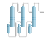
How to Use Wastewater Treatment Symbols
Where to get the symbols?
- Start Edraw, choose Industrial Automation category, and double click Environmental P&ID template to start a new drawing page. This wastewater treatment symbol library will open automatically on the left of the canvas together with some other libraries.
- If your Edraw is already open, you can also click the library button on the top left corner, and navigate Industrial Automation->PID Wastewater Treatment.
Drag and Drop Symbols
When you successfully get access to the symbols, now you can drag and drop required symbols onto the canvas. The shapes you’ve got are vector graphics, which are highly customizable.
Shape Scalable
You are allowed to zoom in the shape as large as you want without losing its clarity.
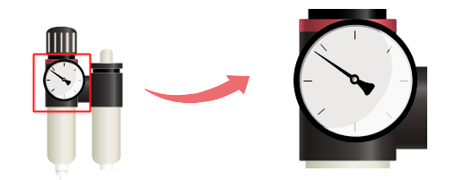
Color Changeable
The filling colors are changeable, so that the symbols can fit whatever themes required.
Tips: To change the filling color for a sub shape, first you need to select the sub shape. There are two ways to select a sub shape. 1. Click on the sub shape you want to change color for a few times until you successfully select it. 2. you can ungroup the shape first (go to Home menu, and click Ungroup button), and click only one time to select a sub shape.
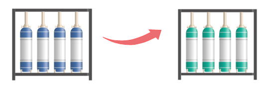
Shape Separable
You are able to pull out the drawing components to create new symbols. To do this, first you need to click Ungroup button to ungroup the shape under Home menu.
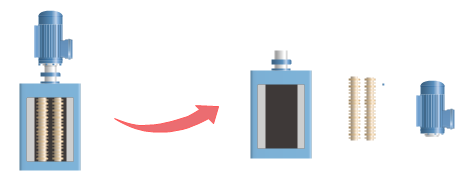
More P&ID Wastewater Treatment Symbols
More wasterwater treatment symbols are available in P&ID designers.
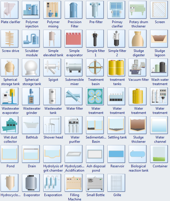
Using Wastewater Treatment Symbols to Design P&ID
Below are some samples containing P&ID waste water treatment symbols. Edraw pre-defined P&ID symbols provides a fast and easy way to design piping and instrumentation diagrams and process flow diagrams.
Water Treatment PFD Template
You don’t have to do much to get an attractive PFD. One simple and fast way is to start from ready-made templates. Here is a simple water treatment pfd example created by EdrawMax, which is available in different formats.
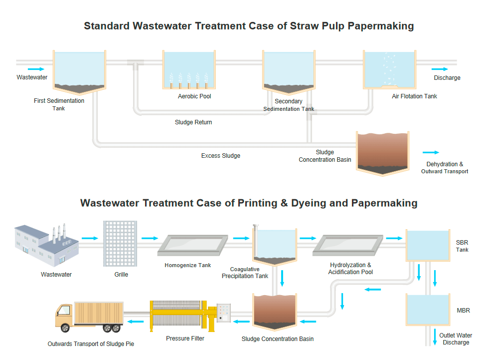
Water Treatment PID Template
Take a look at the free customizable water treatment PID template provided for download and print. With it, you can create your own PID template quickly and easily.
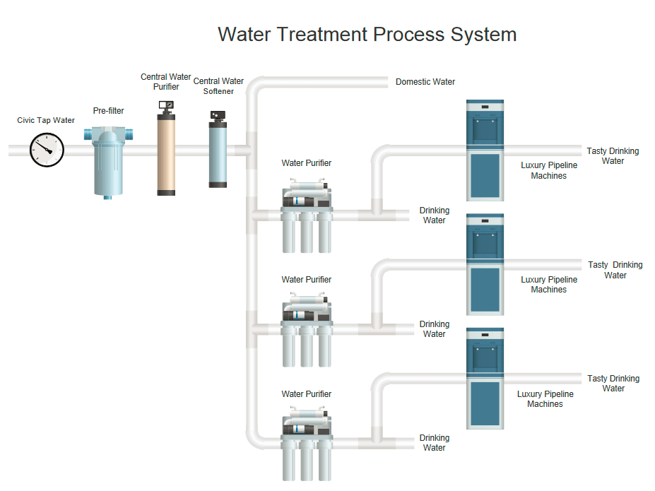
Wastewater Treatment PID Template
Edraw makes your task to make PFDs a snap by offering a wide collection of PFD templates. There is surely one template that can suit your need.
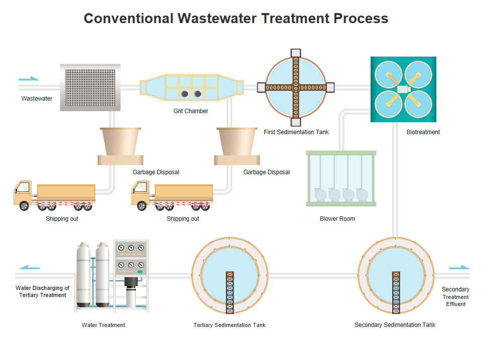
More P&ID Design Materials
P&ID Blower Symbols and Their Usage
Posted by Janice | 01/06/2021 Pre-drawn blower symbols, including blower, air compressor, fume exhauster, gas pump, shaded fan, HVAC compressor, draught fan, etc. Vector symbols help develop accurate and presentation-quality diagrams and documentations.
From the P&ID blower symbols library, you will gain a great range of high quality P&ID blower symbols. These symbols are great resources when you create piping and instrumentation diagram. Here you will have a general overview of the symbols on how they look like and how to use them in diagrams.
Blower Symbols
The following picture shows a screenshot of the blowers symbol library in Edraw. It has a comprehensive collection of vector P&ID blower shapes. You will find blower, air compressor, fume exhauster, gas pump, shaded fan, HVAC compressor, plastic blower, pressure blower, vortex blower, draught fan, and more.
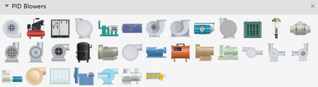
Blower is a low-pressure rotary compressor, esp in a furnace or internal-combustion engine.

Air Compressor is a machine that increases the pressure of air by increasing its density and delivering the fluid against the connected system resistance on the discharge side.

Pressure Fan is a fan that forces fresh air into a mine as distinguished from one that exhausts air from the mine.
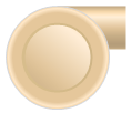
Fume Exhauster is a fan designed to remove dust, fume, gases, and other harmful impurities from the air of production areas.
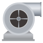
How to Use Blower Symbols
This set of symbols are included in Industrial Automation category of the symbol library. When you start a Process P&ID drawing template, the symbol library will open automatically. You can drag a required shape from the library and drop onto the canvas.
The shapes you’ve got are vector graphics, which are highly customizable.
Size Scalable
You are allowed to scale the shape to any size without loss of the display resolution. There is no blur image anymore.
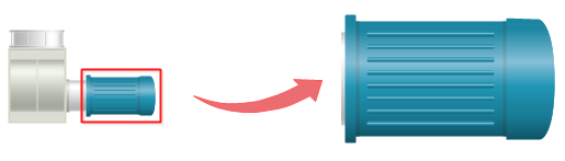
Color Changeable
You are able to freely change filling colors to suit your own theme.
Tips: If you want to change the filling color for a part of a shape, first you need to select the sub shape. Click on the sub shape you want to change color for a few times until you successfully select it (there will be a blue selection frame), then you can change this sub shape with a new color, and with other parts unchanged. Or you can ungroup the shape first (go to Home menu, and click Ungroup button), and change the color for any sub shape freely.

Shape Separable
You are able to pull out the drawing components to create new symbols. First you have to ungroup the shape by clicking on the Ungroup button under Home tab.
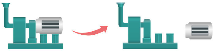
Using Blower Symbols to Design P&ID
Below are some samples illustrating the usage and application of P&ID power symbols. Edraw pre-defined P&ID symbols provides a fast and easy way to design piping and instrumentation diagrams. To discover more examples, you can visit P&ID examples and PFD examples.
Drying Equipment PFD Template
A drying equipment PFD template help you understand drying process easily via information visualization. This template is made by Edraw, downloadable, editable and shareable. View excellent graphics to create PFD.
Ingredient Transfer PFD Template
The visual impact of process flow diagrams created by Edraw can be striking in so many different and unique ways. Have a look at the PFD templates illustrating the transfer process of main ingredients of snack food. With the easily editable symbols, it becomes easier to modify.
Anaerobic Pyrolytic Process Template
PID and PFD templates and examples available at Edraw. Download free for immediate use or modify instantly using our tools. Here is a simple anaerobic pyrolytic process example created by EdrawMax, which is available in different formats.
P&ID Related Articles
P&ID Process Heating Symbols and Their Usage
Posted by Janice | 01/06/2021 Pre-drawn process heating symbols represent batch oven, calendar, circulation heater, compensator, condenser, evaporator, expansion loop, heat exchanger, etc. Vector symbols help develop accurate and presentation-quality diagrams and documentations.
From the P&ID process heating symbols library, you will gain a great range of high-quality P&ID process heating symbols. These symbols are great resources when you create piping and instrumentation diagram. Here you will have a general overview of the symbols on how they look and how to use them in diagrams.
Process Heating Symbols
The following picture shows a screenshot of the process heating symbol library in Edraw. It has a comprehensive collection of vector P&ID process heating shapes. You will find batch oven, calendar, circulation heater, compensator, condenser, evaporator, expansion loop, heat exchanger, hot oil system, simple condenser, power burner, process heater, steam generator, air pre-heater, rotary dryer, solar collector, etc.
Batch Oven is a type of furnace used for thermal processing.
Calendar is a series of hard pressure rollers used to form or smooth a sheet of material such as paper or plastic film.
Condenser is a device used to condense vapor into liquid.
Heat Exchanger is a piece of equipment built for efficient heat transfer from one medium to another.

Steam generator is a form of low water-content boiler, similar to a flash steam boiler.
Simple Guide on How to Use Process Heating Symbols
Where to get the symbols?
- Start EdrawMax, choose Industrial Automation category, and double click Utility-Generation P&ID template to start a new drawing page. This process heating symbol library will open automatically on the left of the canvas together with some other libraries.
- If an Edraw document is already open, you can also click the library button in the top left corner, and navigate Industrial Automation -> PID Process Heating.
Drag and Drop Symbols
When you successfully get the symbols, you can drag and drop required shapes onto the canvas.
Color Changeable
If the current color could not fit your theme, you can freely change filling colors.
Tips:
- To change the filling color for a part of a shape, first you need to select the sub shape. Click on the sub shape you want to change color for a few times until it is successfully selected (there will be a blue selection frame), then you can change this sub shape with a new color, and with other parts unchanged.
- Or you can ungroup the shape first (go to Home menu, and click Ungroup button), and change the color for any sub shape freely.
Shape Separable
To make the shapes tailored to your requirements, you can take out a part or add additional elements easily. To do this, first you need to click Ungroup button to ungroup the shape under Home menu.
Using Process Heating Symbols to Design P&ID
Below are some samples illustrating the usage and application of P&ID process heating symbols. Edraw pre-defined P&ID symbols provides a fast and easy way to design piping and instrumentation diagrams. To discover more examples, you can visit P&ID examples and PFD examples.
Condensation Water Heating PFD Template
This page shows a P&ID template contributed by Edraw for free download. It is ready-made, you can use it directly if suitable. All shapes are editable and you can edit the template instantly.
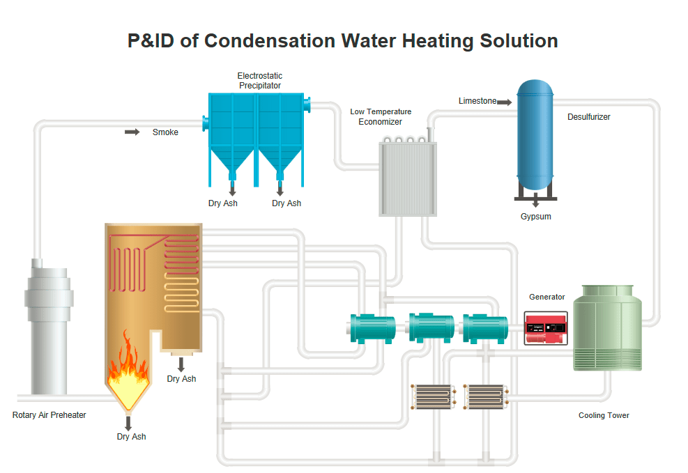
Yeast Production PFD Template
Take a look at a customizable yeast production PFD template. It is provided for free download and print. The symbols used in the template are vector smart shapes with floating action buttons.

SCR System PFD Template
This is an editable template for making high dust SCR system pfd. It is well designed with visually striking elements. Download it for free to get started as quick as possible.

More P&ID Design Materials
P&ID Power Symbols and Their Usage
Posted by Janice | 01/06/2021 Vector P&ID power symbol library contains ready-made power symbols including AC drive, car battery, circuit breaker, DC power supply, generator, insulator, power monitor, rectifier, etc. Lifelike symbols help develop presentation-quality P&IDs and PFDs.
A large collection of P&ID power symbols are provided in Edraw symbol library. Based on advanced quality and comprehensive collection of symbols, it provides an exceptional convenience in making piping and instrumentation diagrams and process flow diagrams.
Free Download P&ID Software and View All Examples
Power Symbols
The following picture shows a screenshot of the power symbol library in Edraw. You will find AC drive, car battery, circuit breaker, DC power supply, generator, insulator, meter gauge, power monitor, rectifier, transformer, transmission tower, electrolyzer, starter, splice box, etc.
Bushing is an insulating lining for an aperture through which a conductor passes.
Car Battery is a type of rechargeable battery that supplies electric energy to a car.
Generator is a device that converts mechanical energy to electrical energy.
Rectifier is an electrical device that converts alternating current (AC), which periodically reverses direction, to direct current (DC), which flows in only one direction.
Transformer is an electrical device that transfers energy between two or more circuits through electromagnetic induction.
How to Use Power Symbols
This set of symbols are included in Industrial Automation category of the symbol library. When you start a Utility P&ID drawing template, the symbol library will open automatically. All the shapes are ready to use and customize.
The shapes you’ve got are vector graphics, which are fully editable. You can easily change the size, color and even separate the shape to get a component if needed.
Shape Scalable
Symbols are allowed to scale up or down in size while keeping high clarity. No blur image anymore.
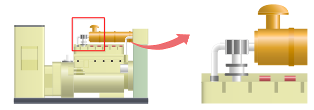
Color Changeable
To make the shapes better fit with your drawing theme, you are can change the filling colors.
Tips:
If you want to change the filling color for a part of a shape, first you need to select this sub shape. Click on the sub shape you want to change color for a few times until you successfully select it (there will be a blue selection frame), then you can change this sub shape with a new color, and with other parts unchanged.
Or you can ungroup the shape first (go to Home menu, and click Ungroup button), and you can change the color for any sub shape freely.
Shape Separable
You are able to pull out the drawing components to create new symbols. To do this, first you need to click Ungroup button under Home menu to ungroup the shape.
For example, if your own substation picture doesn’t require so many gauges, you can simple move them away.
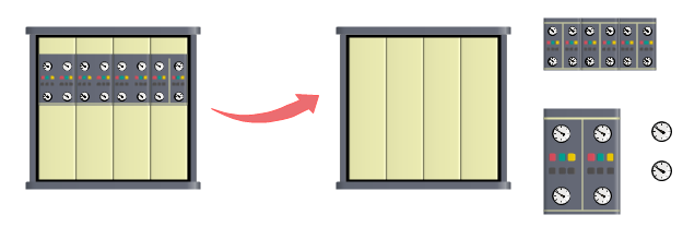
More P&ID Power Symbols
You can reach more power symbols when searching in the library system. There are also abstract power symbols available such as mobile power, power strip, power metal press, power squaring, air powered pump and dc power supply.
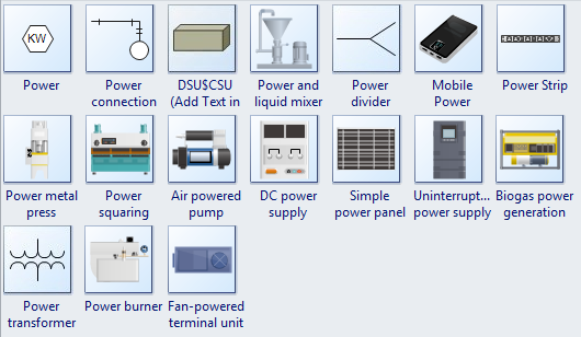
Using Power Symbols to Design P&ID
Below are some samples illustrating the usage and application of P&ID power symbols. Edraw pre-defined P&ID symbols provides a fast and easy way to design piping and instrumentation diagrams. To discover more examples, you can visit P&ID examples and PFD examples.
Power Generation Heating PID
Power Generation Heating PID Template
The power generation heating P&ID template is FREE for you to download and use for personal, business and educational purposes. Try to edit it simply by clicking the action buttons or dragging predefined symbols.

Power Generation PID
Power Generation PID Template
This free customizable power generation P&ID template has been developed to help you when planning a presentation, document archive or workflow analysis. Make some modifications to suit your need. This can be easily handled with the smart action buttons.
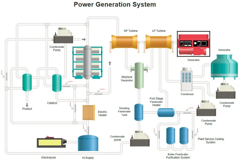
Power Plant PID
Power Plant PID Template
This power plant PID template has been created to make analyzing the workflow of power plan easier through information visualization. You can also gain such PID easily with Edraw through its lifelike pre-drawn pipe and instrument symbols.
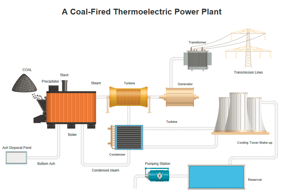
More P&ID Design Materials
P&ID Ductwork Symbols and Their Usage
Posted by Janice | 01/06/2021 Provide various lifelike ductwork symbols, including straight duct, bend duct, junction duct, cross duct, transition, etc. It’s easy to represent P&ID process when you have these vector ductwork symbols.
A wide range of pre-drawn P&ID ductwork symbols are included in Edraw. Fully editable, you can use these symbols for making professional and good looking piping and instrumentation diagrams.
Ductwork Symbols
You can find comprehensive duct shapes with a variety of styles, including straight duct, miter bend, junction up, junction bottom, cross, beveled junction, 3 way junction, Y junction, and transition.

Miter bend is a generic term for any offset or change of direction in the piping. Here also means elbow.

Junction up is used when splitting the flow to the upper direction.

Junction bottom is used when splitting the flow to the bottom direction.

Transition is a fitting used to increase or decrease the duct size, or change the connecting direction.

How to Use Ductwork Symbols
This group of symbols can be found in Industrial Automation category. After you start a process P&ID drawing template, the library named pid ductwork which includes all the above symbols will open on the left of the canvas.
Drag and drop a shape onto the canvas to start drawing. The shapes you’ve got are vector graphics, which are highly customizable.
For this set of duct symbols, you can change the shape length by dragging the selection handles, and change the radius through the floating button. Just as the pictures show below:
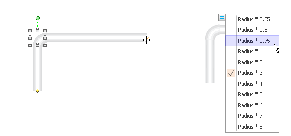
You can also change the filling color if necessary. First click to select the shape, then go to Fill button to choose color options.
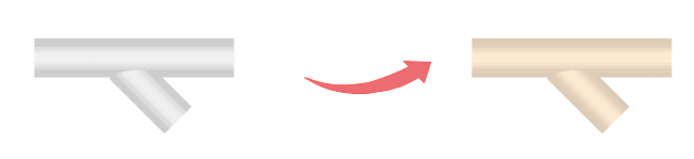
Need fresh looking ductwork symbols for your design? These ductwork symbols are a cinch to pop in. And their crisp, fine detail will make outstanding, easy-to-understand diagrams and presentations to your customers.
Using Ductwork Symbols to Design P&ID
In order to better understand the application of symbols, here we provide some complete P&ID examples using ductwork symbols. Edraw pre-defined P&ID symbols provide a fast and easy way to design piping and instrumentation diagrams.
Production Line PID Template
This PID gives a comprehensive visual overview of the whole bean, residue-less soybean milk production line. Download it free for presentation, archive or other purposes. It is easily editable with smart symbols.
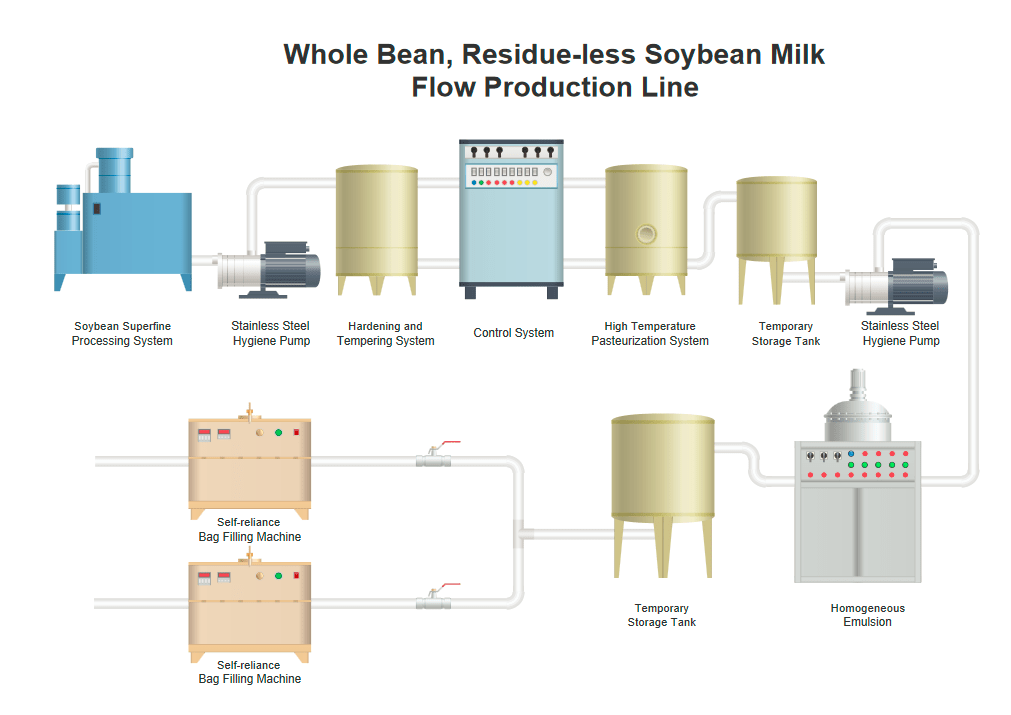
Sulfric Acid PFD Template
Here is a simple sulfric acid PFD example, which is provided for free download and print. Our PFD templates are easy to use in vector format.
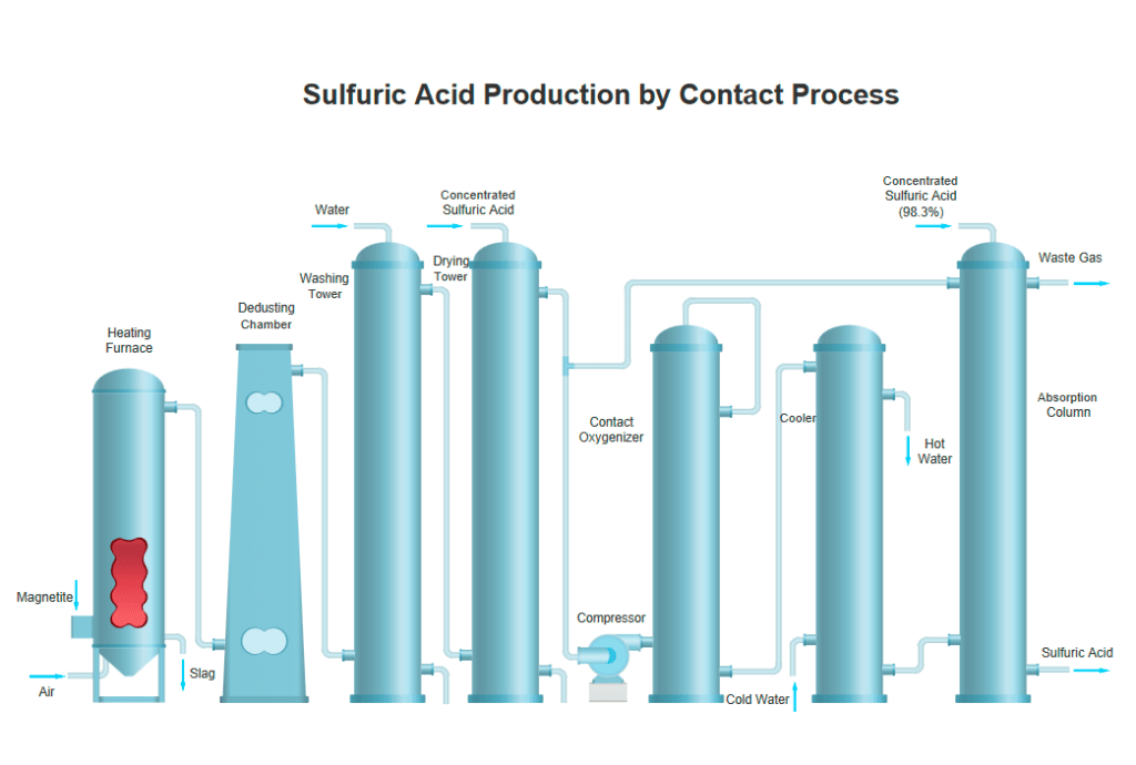
Typical Process Flow Template
This is one of the bonus PFDs made by Edraw PID software that focuses on simplifying the creation of professional PID and PFD. Our templates are free and customizable.
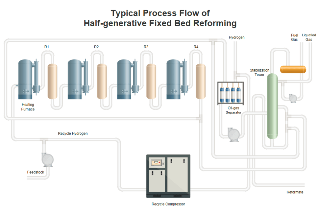
P&ID Related Articles
Comparison between PFD and P&ID
Posted by Janice | 01/07/2021 Learn the differences and common points between PFD and P&ID. Create professional PFDs and P&IDs quickly in powerful but intuitive P&ID software.
Difference between PFD and P&ID
The process flow diagram (PFD) is used in chemical and process engineering. This kind of diagram shows the flow of chemical materials and the equipment involved in the process. In other words, a process flow diagram will tell us the relationships between the major components in the system. Generally, a PFD only contains the major equipment with no more details. And it also won’t depict minor components, piping systems, piping ratings, and designations.
A PFD should include:
- Process Piping
- Major equipment symbols, names and identification numbers
- Control, valves and valves that affect operation of the system
- Interconnection with other systems
- Major bypass and recirculation lines
- System ratings and operational values as minimum, normal and maximum flow, temperature and pressure
- Composition of fluids
Here is a simple process flow diagram example.
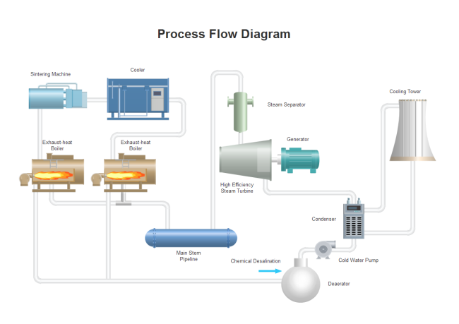
A Piping and Instrumentation Diagram (P&ID) includes more details than a PFD. It consists of both major and minor flows, control loops, and instrumentation. P&ID is sometimes referred to as a Piping and Instrumentation Drawing. P&IDs are mostly used by process technicians and engineering personnel.
A P&ID should include:
- Instrumentation and designations
- Mechanical equipment with names and numbers
- All valves and their identifications
- Process piping, sizes and identification
- Miscellaneous – vents, drains, special fittings, sampling lines, reducers, increasers and swagers
- Permanent start-up and flush lines
- Flow directions
- Interconnections references
- Control inputs and outputs, interlocks Interfaces for class changes Seismic category
- Quality level
- Annunciation inputs
- Computer control system input
- Vendor and contractor interfaces
- Identification of components and subsystems delivered by others
- Intended physical sequence of the equipment
A P&ID should not include:
- Equipment rating or capacity
- Instrument root valves
- Control relays
- Manual switches and indicating lights
- Primary instrument tubing and valves
- Pressure temperature and flow data
- Elbows and similar standard fittings
- Extensive explanatory notes
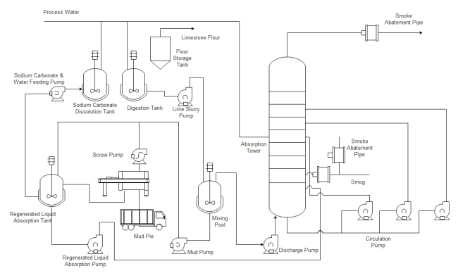
Common Points between PFD and P&ID
In both kinds of diagrams, arrows indicate the flow of material and symbols represent pumps, tanks, valves, and other equipment. The symbols used vary somewhat from organization to organization. So you may see several different symbols that all represent a motor. It is advisable to use a standard set of symbols like those provided by Edraw. Check out the vector PFD symbols and P&ID symbols.
Read More:
A Full Guide to Process Flow Diagram
Basic Knowledge about Piping and Instrumentation Diagram
Posted by Janice | 11/18/2020 The piping and instrumentation diagram , also called P&ID, illustrates the interactions of the piping, equipment and instrumentation of a physical process flow. P&IDs are often used in the process industry to show the process flow, other installed equipment, and instrumentation.
The piping and instrumentation diagram (P&ID) is mostly used in the engineering field. It also plays a crucial role in the design, maintenance, and change of the manufacturing process that it represents. The P&IDs are usually made by engineers who need to design, plan and construct a physical process for a plant.
Differences Between PFD and P&ID
Instrumentation details vary with the degrees of design complexity. For example, simplified or conceptual designs, often called process flow diagrams (PFDs), which provide fewer details than fully-developed piping and instrumentation diagrams (P&IDs). Therefore, a PFD is used only to understand how the process works.
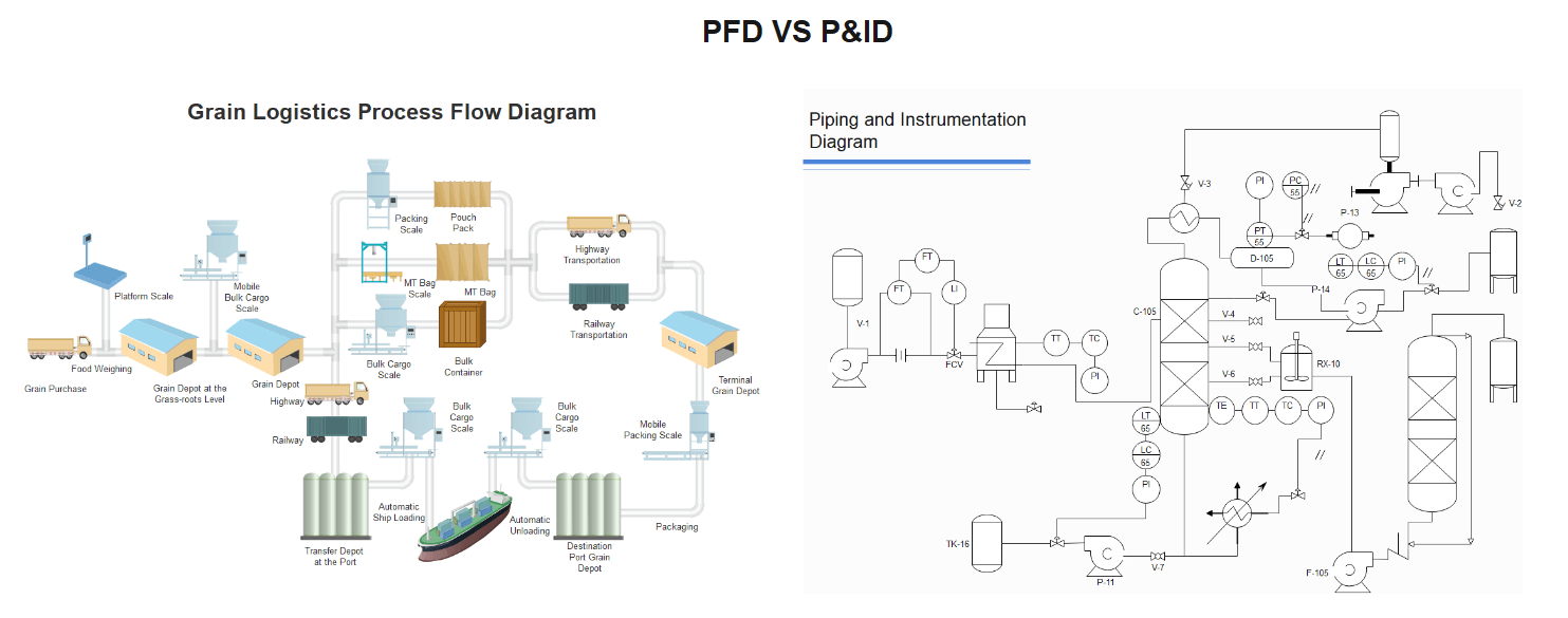
Knowledge About P&ID Symbols
To better understand the process and instrumentation diagram, you need to get familiar with the P&ID symbols used in the piping and instrumentation diagram.
The combinations of letter and number appear inside each graphical element and letter combinations are defined by the ISA standard. Numbers are assigned by users so that the schemes vary in different situations. Some companies use sequential numbering, some will tie the instrument numbers to the process line numbers, and others adopt unique and sometimes unusual numbering systems.
The first letter defines the measured or initiating variables such as Analysis (A), Flow (F), Temperature (T), etc. with succeeding letters defining readout, passive, or output functions such as Indicator (I), Recorder (R), Transmitter (T), etc.
Below are some piping and instrumentation symbols with letters. All the standard P&ID symbols can be found in Edraw Max, which is a powerful and easy-to-use P&ID maker for professionals and beginners.
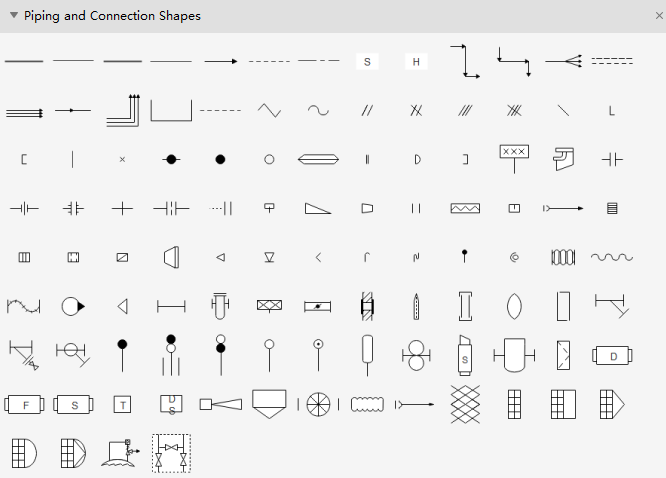
What Should a P&ID Include and NOT Include?
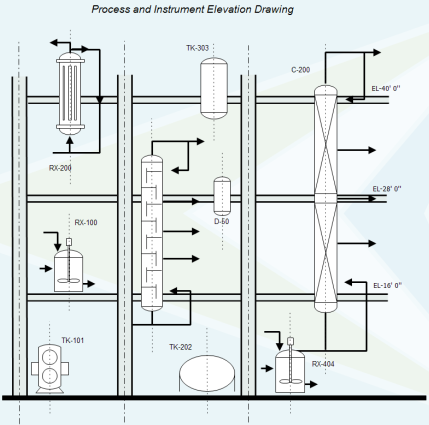
The P&ID is a very common term used in the world of process industries. A process engineer in a manufacturing plant needs to create new and/or modify the already existing P&ID to the as-is plant modifications. All the chemical engineering and related engineering students have also learned about it or at least heard. A P&ID is a detailed graphical representation of a process including the hardware and software (e.g., piping, equipment, instrumentation) necessary to design, construct, and operate the facility. As defined in the PIC001: Piping and Instrumentation Diagram Documentation Criteria by Process Industry Practice (PIP) – a consortium of process industry owners and engineering construction contractors who serve the industry.
A P&ID Should Include:
- Instrumentation and designations;
- Mechanical equipment with names and numbers;
- All valves and their identifications;
- Process piping, sizes and identification;
- Miscellaneous – vents, drains, special fittings, sampling lines, reducers, increasers and swagers;
- Permanent start-up and flush lines;
- Flow directions;
- Interconnections references;
- Control inputs and outputs, interlocks;
- Seismic category;
- Interfaces for class changes;
- Quality level;
- Annunciation inputs;
- Computer control system input;
- Vendor and contractor interfaces;
- Identification of components and subsystems delivered by others;
- Intended physical sequence of the equipment;
- Equipment rating or capacity.
A P&ID Should NOT Include:
- Instrument root valves;
- Control relays;
- Manual switches;
- Primary instrument tubing and valves;
- Pressure temperature and flow data;
- Elbow, tees and similar standard fittings;
- Extensive explanatory notes.
P&ID Examples
Here is a P&ID template for showing the water boiling process and you can customize and remodel it in Edraw Max.
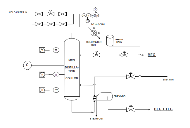
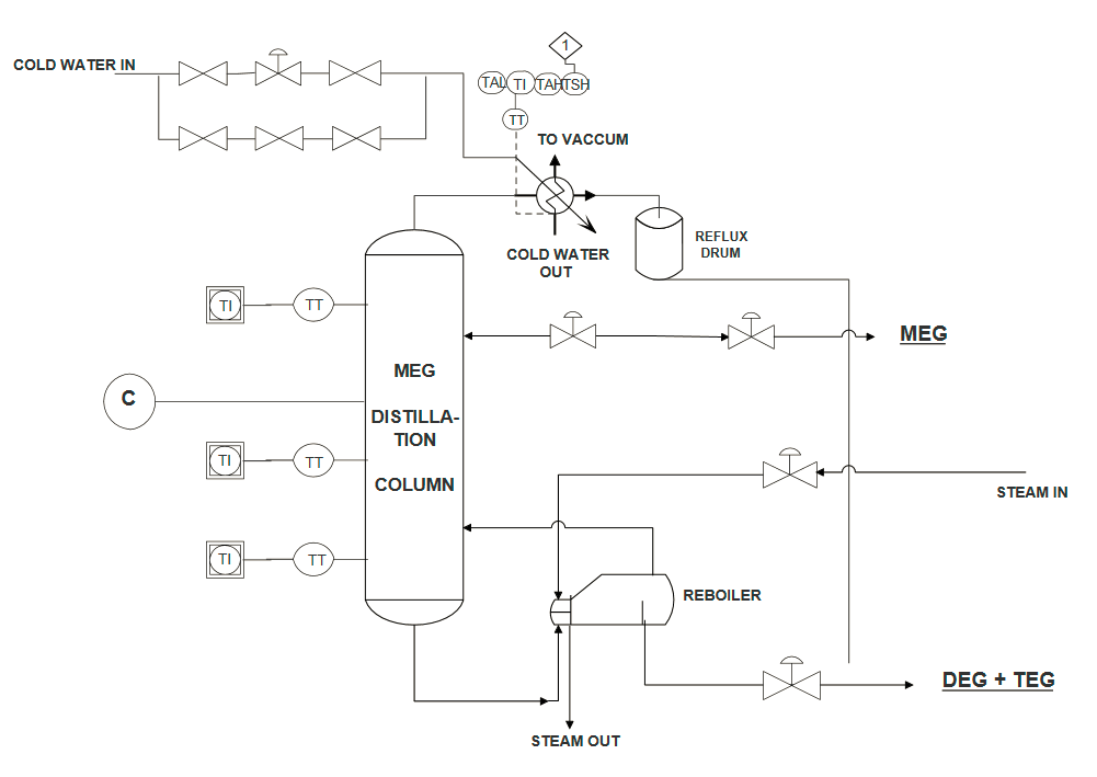
If you want to build a process control system, this template may give you some ideas and get you inspired.
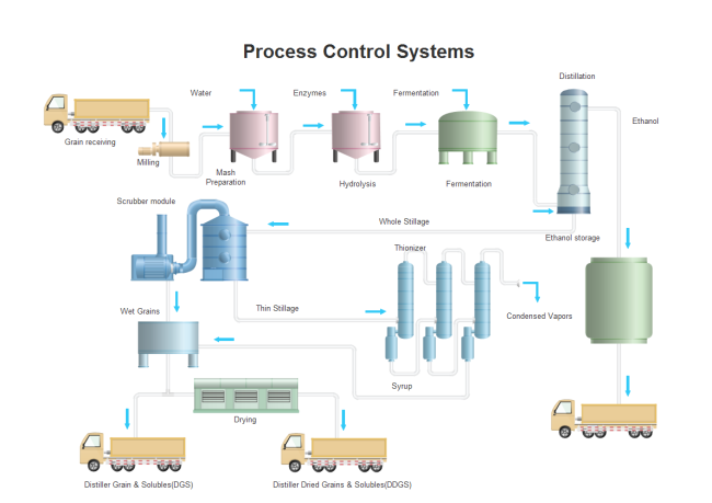

Read More
How to Read Piping and Instrumentation Diagram
P&ID Software for Linux – Easy Piping and Instrumentation Diagram Program
Série de diagrammes P&ID.
Ceci est la première partie d’une série d’articles liés aux diagrammes P&ID. J’ai créé ces articles en pensant aux jeunes ingénieurs qui veulent en savoir plus sur ce système de représentation. J’espère qu’il vous plaira et que vous voudrez en lire plus !
1.P&ID.
Si vous souhaitez en savoir plus sur des sujets tels que les normes et les directives, lisez notre introduction gratuite à ces concepts dans notre article Principes de base du diagramme P&ID – Partie 2 – Normes internationales.
Si vous souhaitez en savoir plus sur des sujets tels que l’identification fonctionnelle et la numérotation des instruments, lisez notre introduction gratuite à ces concepts dans notre article Principes de base du diagramme P&ID – Partie 3 – Identification fonctionnelle et conventions de dénomination.
Le diagramme de tuyauterie et d’instrumentation (P&ID) a une importance fondamentale dans l’automatisation des processus et l’industrie des processus. Il donne une vue d’ensemble de l’ensemble de la boucle de processus de l’installation. Le dictionnaire de l’automatisation, des systèmes et de l’instrumentation dans sa 4e édition définit ce que font les dessins de tuyauterie et d’instrumentation : les schémas P&ID montrent l’interconnexion des équipements de procédé et l’instrumentation utilisée pour contrôler le procédé.
Ils sont utilisés comme élément de communication entre l’ingénierie,
l’exploitation, l’entretien et la construction de la centrale, car ils présentent des informations détaillées sur la centrale concernant l’équipement, la canalisation, l’instrumentation et les services communs. Le P&ID doit être maintenu avec précision et mis à jour.
La création du schéma d’instrumentation ou p&id constitue une phase importante dans la conception d’une usine de procédé.
Il s’agit d’un schéma des systèmes/équipements présents dans une section de l’usine.
Il montre les éléments graphiques nécessaires pour exécuter, surveiller et contrôler des processus spécifiques.
Le dessin P&ID ne décrit pas les réactions chimiques impliquées dans le processus et ne décrit pas non plus les procédures de ceux-ci.
C’est un document essentiel dans l’industrie des procédés.
Toute modification apportée au procédé doit être reflétée dans le schéma, par exemple si une pompe supplémentaire est installée, c’est important car votre sécurité et celle de vos collaborateurs pourraient dépendre de cette action.
Du point de vue du contrôle, ils montrent des informations relatives aux boucles de contrôle, bien qu’il ne soit pas toujours possible de représenter l’ensemble de la structure de contrôle. Pour maintenir la clarté et économiser de l’espace dans ces schémas, la logique complexe n’est pas représentée, elle est représentée dans les schémas logiques ISA-5.2-1976 (R1992).
Du point de vue de l’ingénierie, les schémas de tuyauterie et d’instrumentation (P&ID) constituent la base de l’ensemble de livrables d’ingénierie E/I&C (électrique/instrumentation et contrôle).
Un P&ID est un diagramme qui montre des informations condensées de plusieurs spécialités.
Ce type de documents (les dessins P&ID) montrent, du point de vue du procédé, différentes mesures telles que la pression, le débit, le niveau, etc. et leurs schémas de contrôle respectifs en relation avec les éléments de l’installation et ses conduites d’interconnexion. Ces éléments (équipements mécaniques, tuyauterie, composants de tuyauterie, vannes, conducteurs d’équipement et instrumentation et contrôles) sont représentés par des symboles et des étiquettes. Un ensemble standard de symboles est utilisé pour préparer les dessins des systèmes et des processus de contrôle. Des symboles ont été développés pour représenter tous les composants utilisés dans le traitement industriel et ont été normalisés par l’ANSI et l’ISA.
L’équipement de traitement est représenté à l’aide de symboles tels que des bulles (cercles ou ballons) et d’autres pour indiquer les vannes, les actionneurs, les débitmètres, etc.
Ces symboles sont assemblés sur le dessin d’une manière qui définit clairement le processus.
Les symboles utilisés dans ces schémas sont basés sur les normes suivantes :
Norme ANSI / ISA-5.1-1984 (R1992) Symboles et identification de l’instrumentation, cette norme a été élaborée par ISA-The Instrumentation, Systems and Automation Society (ISA) et l’American National Standards Institute (ANSI).
Norme ISA 5.31983, Symboles graphiques pour la logique d’instrumentation de contrôle distribué/affichage partagé et les systèmes informatiques.
Dans certains cas, les schémas de contrôle sont trop complexes pour être représentés dans un dessin P et ID, dans ce cas, des schémas de contrôle fonctionnels indépendants sont créés.
Principes de base du diagramme P&ID Symbologie ISA vs SAMA.
Pour la conception de diagrammes spécifiques, il est possible d’utiliser la symbologie ISA ou la symbologie SAMA (l’Association of Scientific Apparatus Manufacturers s’est retirée et ne prend plus en charge ses normes, elles ne sont disponibles qu’à des fins historiques et d’information générale).
Bien que le P&ID soit le document global utilisé pour définir le processus, le premier document développé dans l’évolution d’une conception de processus est souvent le PFD (Process Flow Diagrams). Une fois qu’un PFD est publié pour la conception détaillée, la portée du projet a été établie et le développement du P&ID peut commencer.
1.1. Qu’est-ce que le P&ID ?
Prononcé comme P.N.I.D
Il n’y a pas de norme universelle qui spécifie la signification des lettres P&ID. Habituellement, par exemple, le P dans P&ID peut signifier Pipe, Plant ou Process. Le I fait référence à Instrument ou Instrumentation. Le D est pour Dessin ou Diagramme.
Bien que le format final soit le même pour tous les cas, les différents noms donnés à ce type de diagramme sont indiqués ci-dessous :
Schémas de tuyauterie et schéma d’instrumentation.
Diagramme de processus et d’instrumentation.
Schéma de tuyauterie et d’instrumentation.
Dans cet article, pour plus de simplicité, nous désignerons le document par l’acronyme P&ID.
L’objectif du diagramme P et ID est de montrer les informations nécessaires pour comprendre la relation entre la conception conceptuelle du processus, développée à travers les diagrammes PFD et HMB, avec la réalité.
Le PFD et le HMB ne disposent que d’un minimum d’informations liées aux aspects physiques du pipeline ou à l’instrumentation d’un système. Le P&ID fait le lien entre le conceptuel et le réel.
2.1. Au stade de la conception :
Définit la base de conception pour les disciplines de tuyauterie et d’instrumentation. Il est utilisé comme un document qui définit le processus de base, à partir duquel toute l’ingénierie, la fabrication, la construction et l’exploitation seront développées.
Sert à montrer et à convenir des caractéristiques d’exploitation et de maintenance entre l’Ingénieur et le Propriétaire ou entre l’Ingénieur et le Vendeur.
Sert à montrer l’interface avec les fournisseurs d’équipements/packages.
Effectuer la conception/révision HAZOP. Il est utilisé comme document de référence pour la gestion des informations sur la sécurité des processus (PSI) dans la gestion de la sécurité des processus (PSM). Il permet d’obtenir les informations nécessaires pour pouvoir analyser les dangers du processus, les défaillances potentielles et les garanties existantes dans afin de minimiser le plus grand nombre d’erreurs de fonctionnement, de conception ou humaines.
2.2. Pendant le fonctionnement :
Schéma de référence pour l’opérateur, le permis de travail, les modifications de l’usine, etc.
Les techniciens de procédés utilisent des P&ID pour identifier tous les équipements, instruments et tuyauteries présents dans leurs unités.
Les nouveaux opérateurs ou techniciens utilisent ces dessins pendant leur période de formation initiale. Connaître et reconnaître ces symboles est important pour un nouvel opérateur/technicien.
Former les opérateurs de processus. Une partie de la formation poserait des situations et exigerait que les opérateurs soient en mesure de décrire quelle vanne spécifique doit être changée, comment elle doit être changée et ce qu’il faut observer afin de surveiller les effets du changement.
Document d’aide à l’élaboration des procédures d’exploitation et de maintenance.
Développement de procédures de démarrage/arrêt lorsque l’usine n’est pas sous l’influence des systèmes de contrôle de processus installés.
Pendant le SAT, comme une liste de contrôle par rapport à laquelle chaque élément de l’usine est vérifié.
Maintenance des systèmes d’instrumentation et de contrôle. Le schéma procédé et instrumentation ou tuyauterie et instrumentation (P&ID) est probablement le document le plus utilisé par le personnel de maintenance des systèmes de contrôle-commande.
Ingénierie instrumentale. Le diagramme P&ID est le document principal et presque idéal pour synthétiser toutes les fonctions de mesure et de contrôle requises.
Le P&ID est la dernière étape de la conception de l’usine et sert donc de guide pour ceux qui seront responsables de la conception finale et de la construction. Basé sur ce schéma :
Les ingénieurs mécaniciens et les ingénieurs civils concevront et installeront des pièces d’équipement.
Les ingénieurs d’instruments spécifieront, installeront et vérifieront les systèmes de contrôle.
Les ingénieurs en tuyauterie développeront la disposition de l’usine et les dessins d’élévation.
Les ingénieurs du projet élaboreront des calendriers d’usine et de construction.
3.Propriétaire.
Le P&ID est la fille du diagramme de flux de processus (PFD), un produit de discipline mécanique, et de la feuille de bilan thermique et matière (HMB), un produit d’ingénierie de processus.
Ils sont généralement constitués d’ingénieurs de procédés et d’ingénieurs de contrôle lors de la conception et de la construction de l’usine, les ingénieurs de procédés étant les personnes habilitées à valider les modifications.
Le propriétaire du P&ID est généralement l’ingénieur de procédé ou le responsable de l’exploitation.
Cette personne ou ce groupe coordonne les informations qui sont placées dans le diagramme pour s’assurer qu’elles sont cohérentes avec l’objectif du document.
Cette coordination est nécessaire pour réguler les informations fournies par les différents services vers ce document.
Vous trouverez ci-dessous une liste de certaines des différentes spécialités au sein de l’ingénierie qui fournissent des informations pour qu’elles soient reflétées dans ce diagramme :
Ingénierie des procédés : contenu du diagramme, données de processus, description de l’équipement du fournisseur.
Génie mécanique : numéros d’identification des tuyaux (identification, pas de diamètre intérieur), numéros d’équipement et étiquettes, représentation graphique de l’équipement et de la tuyauterie.
Ingénierie de l’instrumentation : numéros d’instruments ; présentation graphique des instruments et câblage/tuyauterie des instruments, type d’instruments.
Ingénierie des commandes/systèmes : descriptions de la logique de commande, communications entre les systèmes de commande.
Génie électrique : puissances moteur, schémas de câblage moteur.
Habituellement, la création et la maintenance de ce type de diagramme incombent au service mécanique.
4.Contenu et conventions P&ID.
4.1. Qu’est-ce qui est inclus dans un P et ID ?
Un diagramme P&ID est une représentation complexe des différentes unités de production présentes dans une usine.
Il est utilisé par des personnes de différentes disciplines.
Les principaux utilisateurs du document après le démarrage de l’usine sont les techniciens de procédé et le personnel d’instrumentation et d’électricité, de mécanique, de sécurité et d’ingénierie.
Cette section aidera à résoudre le problème persistant de longue date des informations confuses sur les PID. Le fait qu’il y ait confusion peut être compris parce qu’il n’y a vraiment pas de norme universelle, nationale ou internationale, multidisciplinaire qui couvre le développement et le contenu des P&ID et spécifie quelles informations doivent figurer sur un P et ID ou même, d’ailleurs, le signification des lettres P et ID.
Toutes les fonctions de contrôle directement liées au processus doivent être indiquées sur le P&ID.
Le diagramme P et ID est un index graphique de tous les principaux équipements de traitement et de toutes les sections principales des instruments de tuyauterie, et montre leurs relations fonctionnelles.
P&ID affiche généralement les types d’informations suivants :
La partie process / tuyauterie comprend :
Les équipements majeurs et mineurs présents dans le procédé/l’usine tels que les cuves, les fûts, les pompes, les réacteurs … montrant
Nom et numéro
Emplacement
Capacité
Pression
Niveau de liquide
Usage
Unités de rechange
Unités parallèles
Résumé des détails de chaque unité
Tous les équipements de tuyauterie et de transport des fluides process et utilitaires. Y compris
Spécification des matériaux de construction
Identification du tuyau
Directions d’écoulement
Taille du tuyau, annexe (épaisseur)
Isolation (épaisseur et type). Informations relatives à l’isolation (chaud ou froid) et au traçage des canalisations ou équipements.
Dispositifs de sécurité.
Inclure les drains, les connexions d’échantillon
La partie Electrique & Instrumentation comprend :
Tous les moteurs, donnant la tension, la puissance et d’autres informations pertinentes comme les boutons utilisés pour les contrôler.
Toutes les fonctions requises pour contrôler le processus comme les indicateurs, les enregistreurs, les contrôleurs, y compris :
Technologie de mesure (symboles graphiques des instruments)
Emplacement de l’instrument
Fonction principale
Numéro de boucle de contrôle de processus
Intervalle
Système utilisé pour effectuer une tâche d’automatisation (instrument local, DCS, PLC…)
Toutes les vannes de régulation, donnant
Type de contrôle
Type de vanne
Type d’action de la vanne
Fonctions de sauvegarde en cas d’échec
Technologie d’actionneur (symboles graphiques des vannes)
Lien de communication entre les systèmes d’instruments et les actionneurs (électriques, numériques pneumatiques/hydrauliques).
Informations sur le débit et la pression
Vannes autocontrôlées
Principaux instruments requis pour exécuter ces fonctions (éléments essentiels pour comprendre les fonctionnalités requises).
Toutes les soupapes de sécurité et régulateurs de pression, indiquant les plages de température et de fonctionnement
Verrouillages et fonctions liées à la sécurité
Selon la taille de l’usine, il sera représenté sur un à plusieurs diagrammes P&I. Généralement, les usines sont divisées en plusieurs zones, chacune correspondant à un ou plusieurs schémas P&ID. Il est recommandé d’étendre l’approche P&ID à d’autres pièces ou systèmes que Process.
Systèmes de détection d’incendie et de gaz : P&I basés sur des plans d’implantation montrant des détecteurs de gaz, d’incendie ou de fumée, un bouton d’urgence…
Systèmes de protection incendie
Équipements du forfait
Analyseurs
4.2. Conventions dans la construction de schémas de tuyauterie et d’instrumentation
Il n’y a pas de normes universelles qui traitent du format à utiliser dans l’élaboration des P&ID. Le format utilisé par la plupart des groupes de conception a été développé au fil de nombreuses années. Cependant, voici quelques lignes directrices qui servent de norme de facto simpliste :
Les appareils sont représentés sous forme d’icônes. Un article n’est affiché que dans un seul P&ID.
Normalement, la disposition de l’installation de l’équipement ainsi que le PFD sont affichés de gauche à droite.
Le processus se déroule de la gauche du P&ID vers la droite.
Les P&ID sont développés sous forme de feuilles de format D (22″ x 34″) ou plus, mais doivent être lisibles lorsqu’ils sont réduits au format B (11″ x 17″) pour une utilisation facile au bureau et sur le terrain.
Les P&ID doivent afficher suffisamment d’informations pour définir le processus sans encombrement. Un à trois équipements avec auxiliaires suffisent normalement pour un P&ID.
Les diagrammes P et ID n’utilisent généralement pas de couleurs pour indiquer ou transmettre leur signification. Les couleurs sont utilisées au niveau de la conception d’un moniteur, mais sont généralement imprimées en noir et blanc.
Pour réduire l’encombrement, un détail typique peut être utilisé pour les composants répétés (voir le drain typique sur la Figure 2-21).
Lorsque la tuyauterie devient complexe, des P&ID auxiliaires sont utilisés.
Ajoutez des notes pour la compréhension et la clarté.
Montrez les tailles relatives des équipements, mais n’incluez pas les élévations ou les dimensions spécifiques. Ils ne montrent pas l’échelle des éléments ou leur géométrie. Ils ne montrent pas non plus d’informations concernant l’orientation de l’équipe ou son emplacement réel.
Chaque ensemble de P&ID doit inclure une feuille de légende, ou des feuilles, pour définir les symboles et les abréviations utilisés.
L’espace libre sur un P&ID devrait faciliter l’ajout de futurs changements de processus ; il est préférable de ne pas commencer avec des P&ID encombrés.
La tuyauterie pneumatique est indiquée là où les informations sont importantes pour communiquer la fonctionnalité des commandes, et les informations du câblage électrique sont présentées (sous la forme de lignes pointillées) pour communiquer l’intention fonctionnelle aux disciplines électriques et d’instrumentation.
Principes de base du diagramme de symboles P&ID – Partie 2.
Normes internationales P&ID.
Récapitulatif des normes de dessin P et ID
Comme vous l’avez lu, il existe plusieurs normes qui définissent les différents symboles qui vous permettent de concevoir un diagramme P&ID. Comme toujours, si nous voulons définir notre standard interne de plante, mieux vaut lire le contenu de tous les standards et sélectionner le meilleur de chacun d’eux.
Il est également important de prendre comme référence des normes qui assurent une mise à jour de leur contenu en fonction de l’évolution de la technologie, cela garantit que notre norme de référence p&id apporte toujours une solution aux différents problèmes de représentation qui se poseront au fil des années.
Quel que soit le choix d’une norme de référence soit une décision qui conditionnera la documentation de l’usine pour une longue période de temps, cela implique que le changement de norme ou de référence sera complexe ou pratiquement impossible.
À titre de référence, plus de 8 ans après la publication d’ANSI/ISA-5.1 en 2009, la plupart des entreprises n’utilisent encore que PIP PIC001 ou ISA-5.1 1984 pour leurs diagrammes P&ID.
Cet article est un résumé des différentes normes existantes sur la symbologie et la méthodologie pour créer un P&ID. Certaines de ces normes, telles que l’ISA, datent de plus de 20 ans et ont été considérées, en l’absence d’autres documents, comme des normes de facto dans l’industrie internationale.
En règle générale, les normes mentionnées dans cet article sont utilisées comme documentation de référence dans le processus de création de normes d’usine de traitement. Chaque usine/organisation adapte le contenu de ces normes à sa propre norme interne en sélectionnant le matériel le plus significatif qui convient le mieux à ses objectifs, générant ainsi ses propres règles internes.
Si, par contre, nous n’avons pas ces règles internes et qu’il n’y a pas de norme établie dans l’usine / l’organisation, normalement la symbologie est généralement basée sur la norme ISA-5.1-2009 (R1992), qui est une excellente solution flexible. document qui définit, principalement, le symbolisme de l’instrument.
Les schémas P&ID doivent être conçus systématiquement et uniformément au sein d’une entreprise. Premièrement, le développement et la mise en œuvre d’un projet P&ID impliquent toujours des ingénieurs professionnels de différents départements.
Les révisions sur le diagramme P&ID permettent de refléter les changements du processus et il est essentiel qu’elles suivent certaines règles chaque fois qu’une révision est nécessaire. Un schéma P&ID aux formats incohérents entraîne confusion et incompréhension de la part des techniciens de procédés.
Sur la base des raisons ci-dessus, un ensemble complet de normes doit être déterminé avant le développement de diagrammes P&ID, soit pour créer un diagramme P&ID à la main, soit sur un ordinateur.
Ces normes définissent le format du symbole et de l’étiquette d’identification pour chaque composant du schéma P&ID. Les symboles de diagramme P&ID sont des représentations graphiques pour les composants de processus, par exemple, l’équipement, la tuyauterie et les instruments.
Les étiquettes d’identification sont une combinaison de lettres et de chiffres utilisés pour reconnaître de manière unique un élément de processus. Actuellement, il existe de nombreuses normes pour les symboles d’instruments et les abréviations de lettres des P&ID. Les plus courantes sont les normes PIP, ISA, ISO, BS et DIN.
Vous trouverez ci-dessous les différentes organisations qui ont élaboré des guides ou des normes sur la symbologie P&ID :
Société d’instruments ISA d’Amérique
DIN Deutsches Institut für Normung
Pratiques de l’industrie du processus PIP
Organisation internationale de normalisation ISO
Norme britannique BS
- Quelles sont les normes P&ID ?
2.1. ISA Instrument Society of America :
2.1.1 ANSI/ISA-5.1-2009, Instrumentation Symbols and Identification, est généralement utilisé dans le domaine de l’instrumentation et du contrôle pour documenter les projets/actifs
Cette norme permet à une personne ayant des connaissances de base sur le contrôle de processus de comprendre quelles mesures sont disponibles dans l’installation et de comprendre comment fonctionne le contrôle du processus en interprétant les documents et les dessins du processus.
Une fonction importante de cette norme est de fournir une liste standard de symboles linéaires à utiliser dans le processus de documentation.
ANSI/ISA-5.1-2009 La dernière version des symboles et identification d’instrumentation comporte des modifications importantes par rapport à la version précédente ISA-5.1-1984 (R1992). Cette version inclut une technologie d’instruments, des systèmes de contrôle et des réseaux informatiques nouveaux et évolutifs.
La dernière version de la norme américaine ANSI/ISA-5.1, Instrumentation Symbols and Identification, est approuvée par le Standards and Practices Board de l’International Society of Automation (ISA) en 2009. Cette norme décrit les symboles d’instrumentation et leurs systèmes d’identification. Cette norme de dessin introduit un mécanisme cohérent qui comprend des schémas d’identification et des symboles graphiques afin de décrire et d’identifier les instruments et les éléments de processus et leurs fonctions. La norme ISA est largement appliquée dans les logiciels de processus commerciaux, qui sont utilisés pour mesurer, surveiller et contrôler la production réelle des processus (ISA, 2009).
2.1.2 Symboles graphiques ANSI/ISA-S5.5-1985 pour les affichages de processus
Le but de cette norme de dessin est d’établir un système de symboles graphiques pour les affichages utilisés par les opérateurs d’usines de mesure et de contrôle des processus. Le système vise à promouvoir :
la compréhension la plus complète et la plus rapide par les opérateurs des informations qui doivent être transmises à travers l’affichage, et l’uniformité des pratiques dans toutes les industries de transformation.
Les avantages qui en découlent sont destinés à être :
une diminution des erreurs de l’opérateur,
un raccourcissement de la formation des opérateurs, et
une correspondance généralement meilleure et plus facile de l’intention de transmission d’informations des concepteurs de systèmes de contrôle avec la réception et l’interprétation des résultats par les opérateurs de la centrale.
La norme de dessin convient à une utilisation dans les secteurs de la chimie, du pétrole, de la production d’électricité, de la climatisation, du raffinage des métaux et de nombreuses autres industries.
2.1.3 ISA (1983) S5.3 Symboles graphiques pour le contrôle distribué et la logique d’instrumentation d’affichage partagé sur les systèmes informatiques
Le but de cette norme est d’établir une documentation pour cette classe d’instrumentation composée d’ordinateurs, d’automates programmables, de mini-ordinateurs et de systèmes à microprocesseur qui ont un contrôle partagé, un affichage partagé ou d’autres fonctionnalités d’interface. Des symboles sont fournis pour interfacer l’instrumentation de terrain, l’instrumentation de la salle de contrôle et d’autres matériels avec ce qui précède. La terminologie est définie sous sa forme générique la plus large pour décrire les différentes catégories de ces dispositifs.
L’intention de cette norme n’est pas d’imposer l’utilisation de chaque symbole de type pour chaque occurrence d’un dispositif générique dans le système de commande global. Une telle utilisation pourrait entraîner une complexité excessive dans le cas d’un dessin de tuyauterie et d’instruments (P&ID). Si, par exemple, un composant informatique fait partie intégrante d’un système de commande distribué, l’utilisation du symbole informatique constituerait normalement une redondance indésirable. Si, toutefois, un ordinateur à usage général distinct est interfacé avec le système, l’inclusion du symbole de l’ordinateur peut fournir le degré de clarté nécessaire à la compréhension du système de commande.
Cette norme p&id tente de fournir aux utilisateurs un symbolisme et des règles d’utilisation définis, qui peuvent être appliqués au besoin pour fournir une clarté d’intention suffisante. La mesure dans laquelle ces symboles sont appliqués à divers types de dessins dépend des utilisateurs. Les symboles peuvent être aussi simples ou complexes que nécessaire pour définir le processus.
2.2 DIN Deutsches Institut für Normung :
2.2.1 DIN 19227 partie 1 Technologie de commande Symboles graphiques et lettres d’identification pour la technique de commande de processus Représentation symbolique des fonctions
Le présent document définit les symboles graphiques pour la représentation de base de l’instrumentation et des commandes de procédé, y compris les équipements de mesure et de commande conventionnels. Cette norme appliquée à la préparation de la documentation de conception pour l’ingénierie de contrôle des procédés intègre les instruments de mesure, d’exploitation et de contrôle existants (DIN, 1993).
Cette norme de dessin est publiée par l’Institut allemand de normalisation.
2.2.2 DIN 19227 Partie 2 Technologie de commande Symboles graphiques et lettres d’identification pour la technique de commande de processus Représentation des détails
Cette norme p&id traite de la représentation détaillée des fonctions telles que spécifiées dans la norme DIN 19227-1. Cette norme est publiée par l’Institut allemand de normalisation.
2.2.3 DIN 40700-40717
Ensemble de normes conçues pour traiter la représentation de plusieurs symboles graphiques standard. Cet ensemble de normes est publié par l’Institut allemand de normalisation.
2.3 PIP -Pratiques de l’industrie des procédés :
2.3.1 PIP PIC001 (2008) Critères de documentation des schémas de tuyauterie et d’instrumentation
La pratique de l’industrie des procédés PIC001 (2008) Les critères de documentation des schémas de tuyauterie et d’instrumentation comportent des symboles pour la tuyauterie et l’équipement de procédé ainsi que la symbologie de base de l’instrumentation.
Cette norme contient des symboles pour les tuyaux et les équipements de traitement, ainsi que la symbologie d’instrumentation de base, et nous pouvons utiliser ce document pour créer un P&ID complet.
La norme PIP ( PIC001) est liée à la norme ISA ( S5.1), car elle utilise les mêmes symboles d’instruments définis par ISA, bien qu’il soit conseillé d’utiliser les deux normes pour permettre une représentation plus à jour des différents systèmes de contrôle. Ces normes sont complémentaires et l’utilisation des deux permet de définir un schéma P&ID plus complet et plus compréhensible.
Le groupe industriel Process Industry Practices (PIP) est une association d’une série d’entreprises membres, dans le but d’harmoniser les normes internes des entreprises membres pour la conception, la construction et la maintenance. Il établit un ensemble de documents harmonisés en tant que pratiques dans diverses disciplines de processus telles que l’énergie, les pâtes et papiers et les produits pharmaceutiques.
La norme P&ID émise par PIP est jointe au PIP PIC001, Piping and Instrumentation Diagram Documentation Criteria, qui définit le format P&ID (taille du dessin, disposition des éléments, format des étiquettes, disposition du texte, etc.), les symboles, les règles de dessin et le schéma d’étiquetage et de numérotation pour les équipements (réservoirs, échangeurs, pompes, réacteurs, etc.), la tuyauterie (canalisations, vannes et raccords), et l’instrumentation et les contrôles (régulateurs, vannes de régulation, transmetteurs, sas, dispositifs de décharge).
2.4 Organisation internationale de normalisation ISO :
2.4.1 ISO 14617 Symboles graphiques à utiliser sur les dessins, schémas, plans, cartes de génie mécanique et de construction et dans la documentation technique pertinente sur les produits
La norme P&ID publiée par les comités techniques de l’Organisation internationale de normalisation (ISO) appartient à la série de normes ISO 14617, Symboles graphiques pour schémas. L’objectif de l’ISO 14617 est de développer une bibliothèque de symboles graphiques harmonisés pour les schémas utilisés dans les applications techniques.
Les sections associées aux P&ID impliquent :
14617-3 spécifie les symboles graphiques pour les connexions fonctionnelles, les pipelines et les joints de connexion
14617-4 spécifie les symboles graphiques pour les éléments de base dans l’actionneur, les actionneurs complets et les dispositifs d’actionnement dans les schémas
14617-5 et 14617-6 spécifient les symboles graphiques pour les dispositifs et fonctions de mesure et de contrôle. Spécifie les symboles pour les boucles de mesure et de contrôle dans les diagrammes à l’aide de symboles et de conventions de dénomination.
14617-8 spécifie les symboles graphiques pour les vannes.
2.4.2 Schémas ISO 10628-1- 2014 pour l’industrie chimique et pétrochimique
Cette norme ne contient pas de symboles d’instruments et de contrôle mais définit la séquence physique des équipements et systèmes de processus.
Norme britannique 2.5 BS :
2.5.1 BS 1646 (1979-1984) Représentation symbolique pour les fonctions de contrôle de mesure de processus et l’instrumentation
L’objectif principal de cette norme est de définir un ensemble de symboles de base pour l’ordinateur de processus, l’interface et les fonctions d’affichage/commande partagées. Il est divisé en quatre parties différentes.
La norme britannique BS 1646 (1-4) a été élaborée par le comité des normes de mesure et de contrôle des processus industriels de la British Standards Institution (BSI) de 1979 à 1984.
Cette norme de dessin fournit un ensemble de représentations symboliques pour les fonctions de contrôle de mesure de processus et l’instrumentation.
La norme est présentée en quatre parties :
La partie 1 et la partie 2 créent un système de symboles qui implique une série de représentations graphiques décrivant les fonctions des équipements de mesure et de contrôle dans un processus. Ce système clarifie uniquement l’identification des fonctions de l’instrument sans permettre des approches de représentation d’instruments spécifiques.
La partie 3 spécifie les symboles d’instruments, tels que les lignes de signal, les appareils de mesure, à utiliser sur les schémas d’interconnexion.
La partie 4 spécifie les symboles pour la représentation de l’ordinateur de processus et/ou des fonctions d’affichage/commande partagées dans la mesure et le contrôle de processus. Les symboles peuvent être utilisés conjointement avec les symboles donnés dans la partie 1 et la partie 2 de BS 1646.
Principes de base du diagramme de symboles P&ID Partie 3.
Conventions d’identification et de dénomination fonctionnelles.
Les ingénieurs aiment dessiner et créer les contours de leurs idées.
Il est généralement nécessaire de pouvoir expliquer vos idées à vos clients ou collaborateurs. Souvent, nous utilisons des dessins pour expliquer une idée qui, autrement, nécessiterait beaucoup de mots pour être expliquée.
Au cours de mes années en tant qu’ingénieur en automatisation, j’ai réalisé de bons dessins qui m’ont aidé à mieux expliquer mes idées.
Une fois le dessin réalisé, il faut identifier les éléments présents dans le schéma P&ID afin de les relier à la réalité. C’est de cette notion que traite cet article.
Ce troisième article sur les schémas P&ID traite de l’identification fonctionnelle et des conventions de dénomination des éléments présents dans un schéma P&ID.
La raison est assez simple, les utilisateurs de systèmes d’instrumentation et de contrôle ont besoin d’une méthode pour identifier l’équipement afin qu’ils puissent administrer l’ingénierie, les achats, l’installation et la maintenance de ces systèmes.
Mais l’identification doit suivre quelques règles de base pour avoir une bonne documentation. Une bonne documentation est la base d’une bonne ingénierie et d’un bon entretien des installations.
La norme d’identification des éléments connectés au contrôle de processus pour la plupart des installations industrielles est basée sur ISA-5.1.
Parfois cependant, vous constaterez que des informations supplémentaires ou des interprétations intéressantes sont ajoutées pour mieux définir les exigences locales, pour répondre aux exigences spécifiques du système ou même pour maintenir la tradition du site.
Il est très important que les normes utilisées dans vos installations soient entièrement définies et rigoureusement suivies. Les directives d’étiquetage doivent être uniformes dans toute la plante.
De plus, la plupart des grandes entreprises ont leurs propres normes internes. Bien qu’il existe de nombreuses différences de détail entre eux, les symboles de base et la structure du code alphabétique sont essentiellement les mêmes. S’il n’y a pas de norme définie par l’usine, la symbologie sera normalement basée sur la norme ISA-5.1-1984 (R1992).
Il existe plusieurs normes nationales relatives à la représentation des schémas de contrôle-commande. Les plus importants en anglais sont BS 1646 et ISA S5.1.
- Règles générales d’identification fonctionnelle P&ID.
Tous les symboles qui apparaissent dans un diagramme P&ID sont formés par des combinaisons de lettres et de chiffres. Un certain jugement est nécessaire pour établir le code alphabétique le plus approprié pour un élément.
Des combinaisons de lettres et de chiffres apparaissent dans chaque symbole p&id.
La signification des lettres du préfixe de l’étiquette dépend de la position. Ces lettres, en général, contiennent suffisamment d’informations pour transmettre la fonctionnalité de la boucle de régulation et permettre de comprendre le sens de la mesure et de la régulation. Parfois, le code de la lettre est insuffisant pour donner une description adéquate de la fonction d’un élément, si cela ne suffit pas vous pouvez fournir des informations complémentaires, soit dans un encadré attaché à votre bulle soit sous forme de texte adjacent.
Le numéro de boucle est unique à chaque boucle. Le numéro de boucle est généralement commun à tous les instruments d’une boucle.
Tous les instruments et éléments seront identifiés en fonction de leur fonction et doivent contenir les numéros de boucle. Les lettres sont une manière abrégée d’indiquer le type d’instrument et sa fonction dans le système. Généralement, deux ou trois lettres sont utilisées. La première lettre identifie la variable mesurée ou initiale, la deuxième lettre est un modificateur et les lettres restantes identifient la fonction.
Les codes alphabétiques doivent être attribués en fonction de la fonction. En règle générale, l’identification fonctionnelle d’un instrument se fera selon la fonction et non selon sa construction. Ensuite, il faut sélectionner le code de la lettre en tenant compte de la fonction de l’élément et non par sa conception ou son installation. Par exemple, la cellule dp dans la figure ci-jointe est désignée comme transmetteur de niveau LT-S233A au lieu de PDT S233A même si elle mesure la pression différentielle. ISA-5.1-1984 (R1992), conseille que l’identification des instruments soit faite selon la fonction et non selon la construction. Il est large dans sa portée et flexible dans son utilisation.
La première lettre d’une identification fonctionnelle fait référence à la variable mesurée. Par conséquent, le positionneur de vanne est désigné par FY L81G, bien que son entrée soit un courant et sa sortie une pression. Cette première lettre correspond à la variable mesurée et, si nécessaire, peut être qualifiée par un modificateur. Des lettres successives décrivent les fonctions de lecture ou de contrôle d’un élément et celles-ci peuvent avoir des modificateurs.
Règle empirique Le nombre total de lettres dans un numéro d’étiquette ne doit pas dépasser quatre.
Selon ISA, il est incorrect d’utiliser les lettres CV pour une fonction autre qu’une vanne de régulation à action automatique.
Afin de garder les diagrammes P&ID clairs et simples, la logique complexe n’est pas montrée, ceci est montré dans les diagrammes logiques ISA-5.2-1976 (R1992).
3.Étiquetage d’identification fonctionnelle P&ID :
Le processus d’étiquetage est un processus bien documenté défini dans plusieurs normes, le numéro d’étiquette typique se compose de deux parties :
une identification fonctionnelle ou un préfixe
et un numéro de boucle ou un suffixe
Selon les circonstances, le deuxième ensemble de lettres est utilisé pour l’indication et l’enregistrement. Ils peuvent également être utilisés comme nom, verbe ou adjectif, auquel cas ils apparaîtront dans le texte ou le discours en tant qu’indicateur, enregistreur, indicateur et enregistrement.
Le schéma de numérotation à deux éléments correspond au format suivant :
où XXXX est le préfixe de balise qui fournit une indication de fonction et YYYY est un identifiant séquentiel pour rendre la balise unique.
Parfois, un élément intermédiaire, tel qu’un numéro de bâtiment ou une désignation de matériau de procédé, est inséré pour indiquer une zone de procédé.
3.1 Préfixe :
Le préfixe est la partie importante de l’identifiant. Dans la majorité des méthodes de marquage p et id liées aux normes, les lettres de préfixe de balise dépendent de la position.
La première lettre indique la propriété physique mesurée ou contrôlée (par exemple, pression, débit, température). La première lettre du numéro d’étiquette est normalement choisie de sorte qu’elle indique la variable mesurée de la boucle de régulation.
Dans l’exemple de diagramme P&ID illustré dans la figure ci-dessus, F est la première lettre du numéro d’étiquette utilisé pour les instruments dans la boucle de contrôle de débit. L’identification fonctionnelle consiste en une première lettre (désignant la grandeur mesurée ou initiatrice ; par exemple, F pour Débit, T pour Température, etc.).
Les deuxième ou troisième lettres sont des modificateurs. Dans la figure ci-dessus, le F en première position indique un élément de contrôle de flux. FT dans la bulle la plus à gauche indique que l’élément est un transmetteur de débit. FC est un régulateur de débit, le symbole FY est un transducteur I/P et FV est une vanne de régulation de débit.
La ligne au centre du symbole du ballon FC indique que le contrôleur est monté à l’avant d’un panneau de commande principal ou DCS. Aucune ligne n’indique un instrument monté sur site, et deux lignes signifient que l’instrument est monté dans un panneau local ou monté sur site. Les lignes pointillées indiquent que l’instrument est monté à l’intérieur du panneau.
Les combinaisons typiques de lettres p&id sont présentées dans le tableau suivant, le tableau est basé sur ISA-5.1-1984 (R1992) :
Les combinaisons typiques de lettres p&id sont présentées dans le tableau suivant , le tableau est basé sur ISA-5.1-1984 (R1992) :
| PREMIÈRE LETTRE | LETTRES SUIVANTES | ||||
| VARIABLE MESURÉE OU INITIATIVE | MODIFICATEUR | LECTURE OU FONCTION PASSIVE | FONCTION DE SORTIE | MODIFICATEUR | |
| A | Analyse (5,19) | Alarme | |||
| B | Brûleur, Combustion | Choix des utilisateurs (1) | Choix des utilisateurs (1) | Choix des utilisateurs (1) | |
| C | Conductivité | Contrôle (13) | proche | ||
| D | Densité/Sp. La gravité | Différentiel (4) | Déviation | ||
| E | Tension | Capteur (élément primaire) | |||
| ESD | Arrêt d’urgence | ||||
| F | Débit | Rapport (fraction) (4) | |||
| g | Jaugeage | Voyant, dispositif de visualisation (9) | |||
| H | Main (manuel) | Élevé (7, 15, 16) | |||
| HH | Élevé Élevé | ||||
| I | Courant (électrique) | Indiquez (10) | |||
| J | Du pouvoir | Scanner (7,24) | |||
| K | Heure, horaire | Taux de changement dans le temps (4,21) | Poste de contrôle (22) | ||
| L | Niveau | Veilleuse légère (11) | Faible (7,15,16) | ||
| LL | Bas bas | ||||
| M | Humidité | Momentané (4, 25) | Moyen, Intermédiaire (7,15) | ||
| N | Choix des utilisateurs (1) | Choix des utilisateurs (1) | Choix des utilisateurs (1) | Choix des utilisateurs (1) | |
| O | Choix des utilisateurs (1) | Orifice, restriction (23) | Ouvert | ||
| P | Pression, Vide | Connexion ponctuelle (test) (26) | |||
| Q | Quantité/Événement | Intégrer, Totaliser (4) | |||
| R | Radiation | Rapport | Enregistrer ou imprimer (17) | ||
| S | Vitesse, Fréquence | Sécurité (8) | Commutateur (13) | ||
| T | Température | Transmettre (18) | |||
| U | Multivariable (6) | Multifonction (12) | Multifonction (12) | Multifonction (12) | |
| V | Viscosité, Vibration, Analyse Mécanique (19) | Soupape, amortisseur, persienne (13) | |||
| W | Poids, Force | Puits ou poche | |||
| X | Non classé (2) | Axe X | Non classé (2) | Non classé (2) | Non classé (2) |
| Y | Événement, État ou Présence (20) | Axe Y | Relais, calcul, conversion (13, 14, 18) | ||
| Z | Position, Dimensions | Axe z | Conducteur, actionneur, élément de contrôle final non classifié | ||
REMARQUES:
- Une première lettre utilisée avec un modificateur est traitée comme une entité de première lettre. Exemple : TDI pour température différentielle.
- Pour couvrir toutes les analyses non décrites par une lettre de choix des utilisateurs. Le type d’analyse doit être défini en dehors de la bulle de marquage.
- À utiliser à la place d’une combinaison de premières lettres. Généralement utilisé pour les enregistreurs/indicateurs multipoints.
- L’utilisation de ces modificateurs est facultative. Exemple : Les lettres H et L peuvent être omises dans le cas indéfini.
- Pour couvrir uniquement les éléments primaires de protection d’urgence, tels qu’un disque de rupture (PSE), et les éléments de contrôle final de protection d’urgence, tels qu’une soupape de sécurité de pression (PSV).
- S’applique aux instruments qui fournissent une vue non calibrée, tels qu’un indicateur de niveau à glace (LG) et des moniteurs de télévision.
- S’applique normalement à la lecture analogique ou numérique.
- Utilisé pour les veilleuses. Exemple : Un feu de position pour un moteur peut être identifié comme EL ou YL, selon que la variable mesurée est respectivement la tension ou l’état de fonctionnement. Utilisé également pour la lumière indiquant le processus. Exemple : Un feu de niveau élevé (LLH).
- Utilisé à la place d’une combinaison d’autres lettres fonctionnelles.
- Utilisé pour les interrupteurs actionnés manuellement ou les contrôleurs marche-arrêt. Il est incorrect d’utiliser les lettres CV suivantes pour autre chose qu’une vanne de régulation auto-actionnée.
- Utilisé généralement pour les appareils solénoïdes et les relais. Pour d’autres utilisations, la signification doit être définie en dehors de la bulle de marquage.
- Ces termes modificateurs correspondent aux valeurs de la variable mesurée, et non aux valeurs du signal. Exemple : Un niveau haut d’un transmetteur de niveau à action inverse doit être LAH.
- Les termes haut et bas lorsqu’ils sont appliqués aux positions des vannes désignent respectivement les positions ouverte et fermée.
- S’applique à toute forme de stockage permanent d’informations.
- Utilisé pour le terme émetteur.
- Utilisé pour effectuer une analyse de la machine (alors que la lettre A effectue des analyses plus générales). À l’exception des vibrations, la signification doit être définie en dehors de la bulle de marquage.
- Ne pas utiliser lorsque les réponses de contrôle ou de surveillance sont chronométrées ou pilotées par le temps/le calendrier.
- Pour signifier un taux de changement dans le temps de la variable mesurée. Exemple : WKIC désigne un contrôleur indiquant le taux de perte de poids.
- Utilisé pour désigner un poste de contrôle des opérateurs, tel qu’un poste de chargement manuel (HIK), ou l’interface opérateur d’un système de contrôle distribué.
- Utilisé aussi pour désigner un orifice de restriction (FO).
- Utilisé aussi pour désigner un enregistreur à balayage de température (TJR).
- Utilisé également pour désigner un interrupteur manuel momentané (HMS).
- Par exemple, un point de test d’analyse est identifié comme AP.
L’utilisation de X pour la première lettre est un cas particulier. À partir de la norme ISA-5.1, la lettre non classée X est destinée à couvrir des significations non répertoriées qui ne seront utilisées qu’une seule fois ou utilisées dans une mesure limitée. Si elle est utilisée, la lettre peut avoir un certain nombre de significations. Lorsqu’elle est correctement appliquée, la lettre X n’apparaît fréquemment qu’une seule fois, ou dans une mesure limitée. Au lieu de cela, les lettres définies par l’utilisateur doivent être utilisées pour les appareils qui apparaissent régulièrement, même rarement. Ainsi, dans de nombreuses installations industrielles modernes, X peut ne pas être nécessaire, car la plupart des appareils apparaissent avec une certaine régularité. Pour ceux d’entre vous qui ont une installation entière remplie d’émetteurs XT ou de transducteurs XY, ne vous inquiétez pas, cette disposition de la norme ISA-5.1 est souvent ignorée. La lettre non classée X est destinée à couvrir des significations non répertoriées qui ne seront utilisées qu’une seule fois ou utilisées dans une mesure limitée. Si elle est utilisée, la lettre peut avoir n’importe quel nombre de significations en tant que première lettre et n’importe quel nombre de significations en tant que lettre suivante. À l’exception de son utilisation avec des symboles distinctifs, on s’attend à ce que les significations soient définies à l’extérieur d’une bulle de marquage sur un organigramme.
La forme grammaticale peut être modifiée au besoin. Exemple : Indiquer peut signifier indicateur ou indiquant.
De nombreux sites utilisent ISA-5.1 comme point de départ.
Bien sûr, l’utilisateur doit documenter clairement les significations spécifiées sur la feuille de légende P&ID du site, et ces significations doivent être maintenues, sans ambiguïté ni changement, pour l’ensemble de l’installation ou, idéalement, pour toute l’entreprise. Le tableau de la feuille de légende peut ensuite être modifié pour incorporer les désignations de lettres attribuées, ou même définir spécifiquement des combinaisons de lettres acceptables ou standard pour l’installation.
L’utilisation dépendra du contexte. Selon les circonstances, les troisièmes lettres Control, Transmit et Compute peuvent également être utilisées comme verbe ou nom, auquel cas elles apparaîtront dans le texte ou le discours comme Controller, Transmitter et Computer, respectivement.
Voici quelques-unes des abréviations p&id les plus courantes comme préfixe :
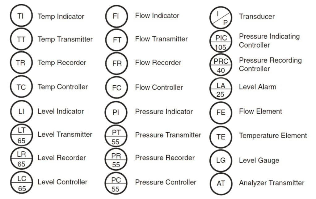
- PIC = Pressure Indicating (Indicator) Controller
- LR = Level Recorder
- TT = Temperature Transmitter
- DAH = Density Alarm High
- DAHH = Density Alarm High High
- LSHH = level switch high-high
- LSH = level switch high
- LSL = level switch low
- LSLL = level switch low-low
- LAL = level alarm low
- PT = pressure transmitter
- PDT = pressure differential transmitter
- AT = analyzer transmitter
- TE = temperature element
- TT = temperature transmitter
- PDSH = pressure differential switch high
- KQL = time quantity light (i.e., time is expired)
- PY = pressure transducer
- ZSO = position switch (open)
- HV = hand valve
- HS = hand switch
essai de traduction en en français

3.1.1 Combinaisons typiques de lettres P&ID
Tableau étendu des combinaisons de lettres typiques pour les équipements d’instrumentation :

3.2 Suffixe
3.2.1 Basé sur le nombre de boucles
En plus des lettres, le groupe de conception en instrumentation et contrôle attribue un numéro de séquence à chaque fonction. Tous les appareils de cette fonction portent le même numéro séquentiel, le numéro de boucle. Un numéro de boucle unique est utilisé pour identifier les dispositifs qui accomplissent une seule action spécifique, généralement une entrée et une sortie pour le contrôle P et ID, une entrée pour l’indication d’une variable de processus ou une sortie manuelle.
Ce numéro, combiné à la lettre de désignation, identifie positivement et de manière unique chaque appareil de cet ensemble.
La numérotation des éléments est conforme à certaines conventions basées sur l’usine.
Il existe deux approches, série et parallèle, dont la série est la plus courante.
En série, chaque canal, boucle ou schéma se voit attribuer un numéro unique, par exemple 47. Quel que soit le code alphabétique, tous ses éléments prennent le même numéro. Par série signifie utiliser une seule séquence numérique pour tous les appareils. Par conséquent, il peut y avoir un FRC-101, un LR-102, un PIC-103 et un TI-104.
Parallèlement, des blocs de numéros sont attribués selon le type ou la fonction de l’instrument, en fonction de son code alphabétique. Il en résulte des éléments similaires dans différentes boucles ayant des numéros contigus.
Ces chiffres peuvent suivre les suggestions de la norme ISA-5.1. Par parallèle, signifie commencer une nouvelle séquence de nombres pour chaque première lettre.
Par conséquent, il peut y avoir un FRC-101, un PIC-101 et un TI-101.
3.2.2 Basé sur le numéro d’emplacement
Le premier chiffre du numéro peut indiquer le numéro de l’usine ; par conséquent, FT-102 est un instrument de l’usine 1.
Une autre méthode d’identification de l’emplacement de l’instrument consiste à utiliser un préfixe, par exemple : 2 (zone), ou 03 (unité) ou 004 (usine 4) qui identifie la zone de service de la boucle : 2-FT-102 est la boucle 102 dans zone 2, ou 03-FT-102 est la boucle 102 dans l’unité 03, ou 004-FT-102 est la boucle 102 dans l’usine 4.
Ces chiffres peuvent également être combinés pour afficher l’unité de surface-usine en un seul numéro : 234-FT-102 est un transmetteur de débit dans la boucle 102, qui dessert la zone 2, l’unité 3 et l’usine 4.
Pour être complètement déroutant, rappelez-vous que le numéro de boucle définit les éléments de la boucle, de sorte que la boucle peut desservir la zone répertoriée ci-dessus, mais un périphérique particulier peut être physiquement situé dans une autre zone.
3.2.3 Diagramme P&ID basé sur le numéro
Une variante de ce système consiste à lier les numéros P&ID à une zone particulière, puis à numéroter séquentiellement les instruments sur cette feuille P&ID. Par exemple, P&ID 25 transporte jusqu’à 100 boucles, ou les numéros de boucle d’instrument 2500 à 2599.
L’élégance de ce système est que vous pouvez trouver le P&ID correct pour un instrument en vous basant uniquement sur le numéro d’étiquette, puisque le numéro d’étiquette inclut le numéro P&ID.
Souvent, le numéro de zone est de toute façon imbriqué dans le numéro P&ID, de sorte que vous connaîtrez également la zone desservie par la boucle simplement en regardant le numéro de boucle.
3.2.4 Équipement majeur basé sur la désignation
La destination qui apparaît à la place du numéro de boucle sur le cercle de l’instrument est un identifiant d’équipement qui est lié à une table de désignation d’équipement maître.
Conventions utilisées pour identifier l’équipement de procédé :
Équipement de procédé Format général XX-YZZ A/B
XX sont les lettres d’identification pour la classification de l’équipement :
C Compresseur ou Turbine
Échangeur de chaleur
H Réchauffeur à feu
P Pompe
Réacteur R
Tour T
Réservoir de stockage TK
Navire V
Y désigne une zone à l’intérieur de l’usine
ZZ est la désignation numérique de chaque élément d’une classe d’équipement
A/B identifie les unités parallèles ou les unités de secours non affichées sur un PFD.
Description supplémentaire de l’équipement donnée en haut du VFI.
