
What is the Most Useful Software in Chemical Engineering?
The List of Most Important Calculation Tools
Ivana Lukec, PhD ( 26.03.2019)

The field of chemical engineering is in constant change, so are available calculation tools and software packages. In fast everyday life, it is a considerable challenge for a chemical engineer to know which tool can serve best for solving a certain problem.
The different packages can be applied to solve typical problems in mass and energy balance, fluid mechanics, heat and mass transfer, unit operations, reactor engineering, and process and equipment design and control.
In this article, we highlight the most important tools and packages with their capabilities, based on the available professional experience of an author, available literature and discussions.
The Figure below summarizes the most useful software packages in chemical engineering:

So, let’s start from the beginning…
General Software for Mathematical Modeling
MS Excel®
It is a known fact that Microsoft Office Excel is a spreadsheet application that features calculation, graphing tools, tables, and a macro programming language – Visual Basic. The main advantage of Excel is that it is available and is widely used in industry and academia. Thus, it is a perfect tool or interface not only to perform calculations but also to connect different software so that the end user can interact with Excel, and behind the scenes, other software such as CHEMCAD, MATLAB etc. is running and reporting the results back to Excel.
It is best used for:
- Built-In functions & formulas – there are a large number of built-in functions defined, such as statistics (MEAN, AVERAGE, t-test), algebraic (SUM, ROUND, LOG, LOG10), logical (IF, FALSE, etc.), reference, database, and information. Those are easy to use in different kinds of formulas.
- Operations with columns and rows – it is easy to find & sort data and use them in replicated formulas etc.
- Plotting – there is a large number of options depending on the needs
- Solver – It is the tool to use within Excel to solve numerically a set of equations, problem optimization including fitting a set of data to a given linear and nonlinear equation and more. Solver is an add-in that needs to be activated to be used.
- Building functions in Visual Basic for Applications – Excel has built-in capability to generate customized functions using Visual Basic for Applications (VBA). This is a powerful tool that can save time for you without becoming an expert in programming as it opens the possibilities to run loops and conditionals on the background. This capability also allows the user to build relatively large equations that are used in several areas of the worksheet (e.g., polynomials for the esti¬mation of specific heat of components) and allows the user to read the calculations easily when looking at the formulas in the cells.
- Link Excel with other software – Excel has become a standard package so that a number of other specialized software use it as a source of information to report data since it is more user-friendly. Therefore, we can use the information in Excel to be loaded in MATLAB, Hysys or CHEMCAD or transferred back to Excel.
Mathworks MATLAB®
MATLAB is one of the most used software packages in engineering in general and also in chemical engineering. Much has been written about this popular software, more than 1500 books serving more than 1 million users.
MATLAB is a programming language. Its operation is based on the use of .m files that can be divided in two classes, scripts and functions. A script is basically a number of operations that we want to perform in a certain sequence. Functions are a particular type of scripts that must begin with the word “function” at the top of them. Functions can be user-defined or typical operations such as equation solving or differential equations. Within MATLAB, we have all the algebraic, statistical functions predefined along with plotting capabilities.
MATLAB has a number of functions that allow solving linear and nonlinear equations (fzero: for one variable alone, fsolve), optimizing a function (fmincon: constrained optimization, linprog: linear programming; fminin or fminsearch: unconstrained optimization; bintprog: binary and integer optimization), and solving differential equations (ode__) or partial differential equations (pdepe).
Some examples of how MATLAB can be used in chemical engineering include:
- Momentum, Mass, and Energy Transfer – There are a number of examples in the transport phenomena field that, even though represent different phenomena, they can be mathematically described using a partial differential equation, the “pdepe” toolbox.
- Distillation Column Operation – McCabeMethod – typical shortcut approach for the initial conceptual estimation of the operation of binary distillation columns
- Modeling of different kinds of process equipment – heat exchangers, pumps, valves, evaporators, columns, reactors etc.
- Reactor design – The models are based on explicit algebraic equations and differential equations. Thus, we use ODEXX function in MATLAB to solve the concentration, temperature, and/or pressure profiles along the operation of such equipment.
- Control loops analysis, control design and tuning.
Mathworks Simulink®
Simulink® (Simulation and Link ) is a software add-on to MATLAB based on the concept of block diagrams that are common in the control engineering areas. It is an environment for dynamic simulation and process control. Each of the blocks can contain a subsystem inside, which is helpful for big problems. We only need to select a number of blocks and with the right button of the mouse, click and select create subsystem.
Simulink is easier to used for engineers because it does not require any programming skills, therefore models can be build using blocks instead of defining functions.
Process Simulators
The simulation, design, and optimization of a chemical process plant, which comprises several processing units interconnected by process streams, are the core activities in process engineering. These tasks require performing material and energy balancing, equipment sizing, and costing calculation. A computer package that can accomplish these duties is known as a computer-aided process design package or simply a process simulator.
The process simulation market underwent severe transformations in the 1985–1995 decade. Relatively few systems have survived and they inclide: CHEMCAD, Aspen Plus, Aspen HYSYS, PRO/II, ProSimPlus, SuperPro Designer, and gPROMS.
Chemstations CHEMCAD
CHEMCAD is Chemstations’ software suite for process simulation. Features include process development, equipment design, equipment sizing, thermophysical property calculations, dynamic simulations, process intensification studies, energy efficiency/optimization, data reconciliation, process economics, troubleshooting/process improvement, Microsoft Visual Basic etc.
The CHEMCAD suite includes six products that can be purchased individually or bundled as needed for specific industries, projects, and processes.
- CC – steady state simulations of continuous chemical processes, features libraries of chemical components, thermodynamic methods, and unit operations, enabling you to simulate processes from lab scale to full scale. Ideal for Users who want to design processes, or rate existing processes, in steady state.
- CC – dynamics is used to conduct dynamic flowsheet analysis, operability check-out, PID loop tuning, operator training, online process control and soft sensor functionality. Ideal for users who want to design or rate dynamic processes.
- CC-THERM is used for sizing heat exchangers, covers shell-and-tube, plate-and-frame, air-cooled, and double-pipe exchangers. Rigorous designs are based on physical property and phase equilibria data.
- CC-BATCH allows you to design or rate a batch distillation column.
- CC-SAFETY NET – used for analysis of any pipe network with the piping and safety relief network simulation software.
- CC – FLASH – Used to calculate physical properties and phase equilibria (VLE, LLE, VLLE) for pure components and mixtures with incredible accuracy. All products within the CHEMCAD suite feature CC-FLASH capabilities.
ASPEN HYSYS & ASPEN PLUS
Two similar software packages with all the functionalities that process simulator should have are also the most widespread among chemical engineers. AspenTech has a wide portfolio of modeling tools, among them most important and most known are process simulation tools Aspen Hysys and Aspen Plus.
Aspen HYSYS (or simply HYSYS) is a chemical process simulator used to mathematically model chemical processes, from unit operations to full chemical plants and refineries. HYSYS is able to perform many of the core calculations of chemical engineering, including those concerned with mass balance, energy balance, vapor-liquid equilibrium, heat transfer, mass transfer, chemical kinetics, fractionation, and pressure drop. HYSYS is used extensively in industry and academia for steady-state and dynamic simulation, process design, performance modeling, and optimization.
Aspen Plus is a process modeling tool for conceptual design, optimization, and performance monitoring for the chemical, polymer, specialty chemical, metals and minerals, and coal power industries. It can also be used for mass and energy balances, physical chemistry, thermodynamics, chemical reaction engineering, unit operations, process design and process control.
In general, it can be said that Aspen Plus is better tool for chemical process design such as fine chemistry, chemicals, pharma, etc., whilst HYSYS is best for hydrocarbon, petrochemical, petroleum operations such as natural gas, liquified gases, crude oil etc…
Specialized Software
Computational Fluid Dynamics
Computational fluid dynamics, known as CFD, is the numerical method of solving mass, momentum, energy, and species conservation equations and related phenomena on computers by using programming languages.
CFD and multiphysics modeling and simulation can be applied to many science and engineering disciplines. The main areas in chemical engineering are the following:
- Combustion processes,
- Food process engineering,
- Fuel cells, batteries, and supercapacitors,
- Microfluidic flows and devices,
- Pipe flows and mixing,
- Reaction engineering.
The basics of CFD are partial differential equations and thus knowledge of numerical mathematics is essential to solve them with appropriate numerical technique.
Since these conservation equations are designed and solved on computers, knowledge of programming languages, such as FORTRAN, C++, Java, or MATLAB is equally important.
CFD-based software modeling tools, popular in scientific and engineering communities, are ANSYS CFX, ANSYS Fluent, ANSYS Multiphysics, COMSOL Multiphysics, FLOW-3D, STAR-CD and STAR-CCM+, and an open-source software tool OpenFOAM. Other CFD-based software tools, such as AVL FIRE or ANSYS Polyflow, are also available on the market, but they are specialized for particular physical systems, such as internal combustion engines, power trains, polymers, glass, metals, and cement process technologies.
The most widely used commercial software tools, such as ANSYS Fluent, STAR-CD, and STAR-CCM+, are based on finite volume method, whereas ANSYS CFX uses finite element-based control volume method. On the other hand, COMSOL Multiphysics is based on finite element method.
Review of open source process simulators
It is not always necessary to use only expensive simulation packages
SimulateLive.com 07.04.2018.

One of the most important reasons that process simulation is not used more across the industry is the price of the simulation packages. Some of those most used software packages come together with the price reaching tens of thousands of USD for one license. Although, this price can be easily justified with the benefits achieved, it still very often remains an obstacle, especially for small engineering companies. Thanks to the hard-working and generous groups of experts who share their knowledge with all of us, this article presents some of the available open source process simulators. However, they are not allowed to be used commercially.
1. DWSIM
DWSIM is a software for modeling, simulation, and optimization of steady-state chemical processes. It is the most popular open source simulation software that can be used for Windows, Linux and Mac OS X. It is written in Visual Basic and features a comprehensive set of unit operations, advanced thermodynamic models, support for reacting systems, petroleum characterization tools, and a fully-featured graphical interface. Definitely should be one of the solutions on the top of your list if you are new in the process simulation or would like to get the results for a less complex process problem. It has the great number of important features, most of those that we are used to from using standard simulator packages. Some of them are:
- VLE, VLLE, SLE and Aqueous Electrolyte calculations using Equation of State, Activity Coefficient and Chao-Seader models,
- Supports CAPE-OPEN Unit Operations and Thermo 1.0/1.1 Property Packages,
- Exposes Property Packages as CAPE-OPEN 1.1 Thermodynamic Equilibrium and Property Calculators,
- Supports ChemSep’s Component Database and Column Model,
- Process Flowsheet Diagram (PFD) Drawing Interface,
- Rigorous Distillation/Absorption Column models,
- Support for Chemical Reactions and Reactors,
- Characterization of Petroleum Fractions using bulk properties and/or ASTM/TBP, distillation curves and creation of Hypothetical Components using UNIFAC groups,
- Multivariate Optimization and Sensitivity Analysis utility,
- Excel Interface for Thermodynamic Calculations,
- Standalone Thermodynamics Library,
- Component Creator Utility for user-defined components.
One of our future articles will bring the analysis of some simple calculations using DWSIM.
Until then, you can find out more about DWSIM and download the software here: https://sourceforge.net/projects/dwsim/files/?source=navbar
2. COCO simulator
The other process simulator that comes with the bunch of features is called COCO. Behind this exotic name is another free-of-charge process simulator, non-commercial, graphical, modular and CAPE-OPEN compliant simulator for steady-state and sequential simulation process modeling. It was originally intended as a test environment for CAPE-OPEN modeling tools but now provides a free chemical process simulation for students. It is an open flowsheet modeling environment allowing anyone to add new unit operations or thermodynamics packages.
A list of features includes:
- Thermodynamics for Engineering Applications,
- the CAPE-OPEN Unit-operations Simple package is shipped with COCO. It contains a splitter, a mixer, heat exchangers, pumps and reactors amongst other unit operations.
- Reaction Numerics package.
The free package comes with certain limitations in calculations, such as limitation to 40 compounds, but can definitely be used for some simplified or short-cut modeling. What is especially beneficial is the collection of free sample flow sheets available for download at their web-site: https://www.cocosimulator.org/index_sample.html
Sample flow sheets include prepared examples such as:
- Pressure swing azeotropic distillation of methanol and acetone,
- Benzene-toluene-xylene divided wall column,
- Methanol synthesis from syngas,
- Combined heat and power cycle.
To download the software, follow this link: https://www.cocosimulator.org/index_download.html
3. OPENMODELICA
OPENMODELICA is an open-source Modelica-based modeling and simulation environment intended for industrial and academic usage. Its long-term development is supported by a non-profit organization – the Open Source Modelica Consortium (OSMC). Modelica is not a process oriented simulator such as DWSIM, but a general modeling tool and the platform closer to Matlab.
OpenModelica is a comprehensive compilation and simulation environment based on free software distributed in binary and source code form for research, teaching, and industrial usage.
There is a long list of industrial and university members including ABB, Siemens, Evonik etc.
Modeling using OpenModelica enables:
- Multi-domain modeling
- Hybrid modeling
- Visual component modeling etc.
One example of how to use OpenModelica is ABB OPTIMAX® model that provides advanced model-based control products for power generation and water utilities. Plant models are typically formulated in Modelica and deployed through FMI 2.0. The optimizing control applications maximize the efficiency and provide more flexibility to large conventional power plants that face frequent load ramps and start-ups. Moreover, they aggregate small renewable units to large virtual power plants. This enables renewables to provide grid services like power/frequency control, achieving grid stability despite of high penetration of renewable power and raising revenues. ABB uses several compatible Modelica tools, including OpenModelica, depending on specific application needs. OpenModelica provides debugging features that help to save a lot of time during model development.
To download OpenModelica software, please follow this link:
https://openmodelica.org/download/download-windows
Complete List of Process Simulators
Review of simulation software for industrial plants
SimulateLive.com 22.05.2017.

Steady-state and dynamic plant simulation are powerful tools that help engineers create optimal process designs to analyze plant operations, to develop performance improvement strategies, monitor and optimize operations and much more.
We are providing a full list of process simulator packages with their key characteristics. They are available for different industries, purposes, scales and under different commercial conditions. While some of them are very expensive, there are as well affordable ones and even a couple of them that are totally free of charge. So, no more excuses for not using process simulation tools. On this list, there will definitely be something for you:
Aspen Plus
Developer: AspenTech
On the market: commercial
Main Features:
Aspen Plus is one of the most known process simulators in industry and also one of the most expensive ones. It enables a wide range of calculation possibilities for the design, operation, and optimization of safe, profitable manufacturing facilities. It enables the steady-state and dynamic simulation of petrochemical, chemical and pharmaceutical processes, including non-ideal, electrolytic, and solid systems. Mixed solution methodologies can be used to achieve fast calculation and provide full specification flexibility. Leverage modeling investments by scaling from single models to full facility flowsheets.
CADsim Plus
Developer: Aurel Systems Inc.
On the market: commercial, flexible licensing
Main Features:
CADSIM Plus is chemical process simulation software that can perform mass and energy balances and simulate dynamic conditions. It is a first-principles dynamic chemical process simulator and a full-featured Computer Assisted Drawing (CAD) front-end in one package. CADSIM Plus includes a comprehensive set of generic process modules and has a number of optional module libraries for various applications. CADSIM Plus can also be used to develop complex dynamic simulations with control logic and batch operations.
Chemcad
Developer: Chemstations Inc.
On the market: commercial
Main Features:
Chemical process simulation software that includes libraries of chemical components, thermodynamic methods, and unit operations to allow steady-state and dynamic simulation of continuous chemical processes from lab scale to full scale. Ideal for users who want to design processes, or rate existing processes, in steady state. Dynamic process simulation software that takes steady-state simulations to the next level of fidelity to allow dynamic analysis of flowsheets. The possibilities are endless: operability check-out, PID loop tuning, operator training, even online process control and soft sensor functionality and is ideal for users who want to design or rate dynamic processes.
ChromWorks
Developer: YPSO Facto
On the market: commercial
Main Features:
YPSO Facto is chromatographic process simulation software and allows a rational use of experimental data and simulation of standard single columns as well as complex continuous multi-column processes. A software package for the simulation of Ion Exchange processes allows simulating very different situations ranging from amino acids purification, organic acid recovery or hydrometallurgy.Based on proven technical considerations and complemented by a cost evaluation module, this powerful and user-friendly simulation tool is designed to match the approach and needs of chemists and biochemists.
COCO
Developer: AmsterCHEM
On the market: open source
Main Features:
COCO is a cape open to cape open simulation environment with modules presented with interesting names such as: COFE – the CAPE-OPEN Flowsheet Environment is an intuitive graphical user interface to chemical flowsheeting. COFE displays properties of streams, deals with unit-conversion and provides plotting facilities.
TEA – COCO’s Thermodynamics for Engineering Applications, is based on the code of the thermodynamic library of ChemSep and includes a data bank of over 430 commonly used chemicals. The package exhibits more than 100 property calculation methods with their analytical or numerical derivatives.
COUSCOUS – the CAPE-OPEN Unit-operations Simple package is shipped with COCO. It contains a splitter, a mixer, heat exchangers, pumps and reactors amongst other unit operations. ChemSep-LITE, a limited version of ChemSep with a maximum of 40 compounds and 300 stages, can serve as an equilibrium distillation unit operation in COCO.
Simulation package can be downloaded here.
Design II for Windows
Developer: WinSim Inc.
On the market: commercial
Main Features:
Design II performs complete heat and material balance calculations for a wide variety of pipeline and processing applications. The simulator’s easy-to-create flowsheets allow process engineers to concentrate on engineering, rather than computer operations. A minimum amount of input is required to utilize DESIGN II FOR WINDOWS. WinSim’s simulator features such as sizing and rating of heat exchangers and separators, within the flowsheet. The DESIGN II FOR WINDOWS database contains 1,200+ pure components, and others can be added via CHEMTRAN. Also included is a crude library with 38 world crudes, already characterized.
DWSim
Developer: Daniel Medeiros
On the market: open source
Main Features:
DWSIM is an open source, CAPE-OPEN compliant chemical process simulator for Windows and Linux systems. Written in VB.NET and C#, DWSIM features a comprehensive set of unit operations, advanced thermodynamic models, support for reacting systems, petroleum characterization tools and a fully-featured graphical interface. Some of the features are VLE, VLLE and SLE calculations using equation of state, supports CAPE-OPEN Unit Operations and Thermo 1.0/1.1 Property Packages, supports ChemSep’s Component Database and Column Model, Process Flowsheet Diagram (PFD) Drawing Interface, Rigorous Distillation/Absorption Column models, Support for Chemical Reactions and Reactors, Characterization of Petroleum Fractions using bulk properties and/or ASTM/TBP distillation curves and creation of Hypothetical Components using UNIFAC groups, Multivariate Optimization and Sensitivity Analysis utility, Excel Interface for Thermodynamic Calculations and more…
Download available here.
DynoChem
Developer: Scale-up Systems
On the market: commercial
Main Features:
DynoChem is process development and scale-up software for scientists and engineers working in the pharmaceutical industry. DynoChem has been used in Big Pharma for over a decade. Companies deploy the software at R&D sites and Primary Manufacturing facilities globally for routine use by scientists and engineers to help facilitate key corporate objectives.
Roll-out of the software is controlled by each company and its adoption is assisted by on-site training, technical user support on projects, regional user group meetings and targeted application webinars. In addition, tools are provided for companies to develop their own template models, implement multi-site equipment databases and also train in-house experts.
EMSO
Developer: Alsoc Project
On the market: open source
Main Features:
EMSO is the acronym for Environment for Modeling Simuation and Optimization. The ALSOC project develop and maintains specifications of a modeling language suited for the synthesis, simulation, optimization, and process control of general processes. It is entirely written in C++, currently available for Windows and Linux but can be compiled for other platforms if desired. It is an Equation-Oriented simulator and has a large set of built-in functions. Models are written in a modeling language, so the user does not need to be a programmer. It supports static simulation and dynamic simulation. A graphical user interface can be used to model development, simulation execution, and results visualizing. It has the ability to use a system of PlugIns where the user can embed code written in C, C++ or FORTRAN into the models.
The download is possible from this site.
Eq-comp
Developer: Eq-comp
On the market: commercial, services paid per calculation basis
Main Features:
EQ-COMP is a complex chemical engineering process simulation software tool for automatically calculating vapor-liquid equilibrium properties of pure hydrocarbons and binary and multi-component mixtures of hydrocarbons. EQ-COMP is written using software tools like MS Excel and VBA. EQ-COMP can predict vapor-liquid equilibrium properties for hydrocarbon mixtures using Peng-Robinson cubic equation of state. The possible components can include non-polar hydrocarbons, mildly polar hydrocarbons, non-polar inorganic gases or mildly polar inorganic gases. Q-COMP chemical process simulation software can be used for pressure vessel design, distillation column design, natural gas pipeline design and designing of other hydrocarbon handling equipment and can also be used for oil well simulation and in natural gas contract drafting. EQ-COMP can predict phase equilibrium properties of multicomponent hydrocarbon mixtures very accurately. It has been designed to provide correct properties for almost any composition of the 100 + hydrocarbons and 3 inorganic gasses.
gPROMS
Developer: PS Enterprise
On the market: commercial
Main Features:
gPROMS FormulatedProducts is PSE’s new platform for the integrated design and optimization of formulated products and their manufacturing processes. It allows scientists and engineers to screen formulations for end-user attributes, determine whether they can be manufactured efficiently, and explore the design space of the whole formulation and manufacturing chain. gPROMS is an advanced mechanistic process modeling tool, integrating crystallization, solids processing and oral absorption on a single platform. It builds on and strengthens the existing capabilities of gCRYSTAL®, gSOLIDS® and gCOAS® in a systems-based approach that links product performance to process and formulation parameters. Users can screen formulations for end-user attributes, identify risk factors and optimize the entire formulation and manufacturing chain. Application areas include crystallization, solids processing, life sciences, food & dairy and more.
Hydroflo
Developer: Tahoe Design Software
On the market: commercial and academic version for students and educators free of charge
Main Features:
HYDROFLO determines the steady-state flows and pressures and other operating parameters in a single source/single discharge, gravity and pumped flow systems. Pumped systems can be closed loop or open reservoir/tank systems and virtually any incompressible fluid system commonly found in industrial process, water supply, wastewater treatment, fire protection, chemical process, mine de-watering, irrigation and HVAC industries can be modeled.
HYDROFLO’s drag-and-drop workspace gives the designer a vertical space view of the system. Group element data editing makes large scale changes to a design very easy. Instant feedback of analysis results are available simply by hovering over elements. Complete detailed PDF reports of system elements, Hydraulic Grade Line and pump plots are included. NPSHA calculations and NPSHR comparisons are made.
Hysys
Developer: AspenTech
On the market: commercial
Main Features:
Aspen HYSYS, similar to Aspen Plus but dedicated to process simulation of oil, gas and refining processes. It allows using industry-specific unit operation models and powerful tools to optimize operating parameters for feedstock changes. Aspen HYSYS Petroleum Refining now also has a complete suite of rigorous kinetic models to support all major refinery processes. Software allows using the simulation to make better planning and optimization decisions with the support of calibrated models. It also includes tools to easily import and export petroleum assays to and from Aspen PIMS with the new Aspen Assay Management. You can also automate the export of rigorous reactor models to Aspen PIMS (LP software).
HSC Chemistry
Developer: Outotec
On the market: commercial
Main Features:
With the tool is possible to carry out thermodynamic and mineral processing calculations on a standard computer quickly and easily. Essential software toolkit for process research, development, design, and digitalization, as well as for estimating process efficiencies, yields, and environmental footprints.
The modules included in HSC Chemistry have been designed to help solve real problems in industrial processes or to decrease the amount of expensive trial-and-error chemistry at the R&D stage. The software contains 24 modules connected to 12 integrated databases. The modules operate like independent programs, each with its own interface and can be used to create process models for hydrometallurgical and pyrometallurgical systems, as well as for minerals processing and physical recycling systems.
IndissPlus
Developer: RSI
On the market: commercial
Main Features:
IndissPlus, based on First Principles of Chemical Engineering, accurately models process behavior at normal operations or during transient periods, whether the models are part of a dynamic study or incorporated into an Operator Training Simulator (OTS) solution
The application has a rich library of Thermodynamics Packages, Pure Components, and Unit Operation Modules. If 3rd party proprietary components, thermodynamics packages or chemical reactor models are required they can be seamlessly integrated within the IndissPlus platform, by taking advantage of the multi-layer component architecture.
IndissPlus incorporates a Process Diagram Builder to enable users to interactively build their flowsheets using the menus, dropdowns or drag and drop capabilities. Unit Operation detail can easily be specified through each Unit Operation’s Faceplate by filling in the appropriate information in the form of a datasheet.
ITHACA
Developer: Element Process Technology
On the market: commercial
Main Features:
It is a low-cost dynamic process simulator for chemicals, mining & minerals. The features include graphical interface for process flow diagrams, real-time information about the degrees of freedom of the simulation (global) and by equipment (local), integration with Microsoft Excel by means of an add-in, results exporting in clear text, dynamic simulation MSO export (to be used by the EMSO process simulator), updated thermodynamic library with the most recent models tools for oil assay modeling by means of pseudocomponents, specific library for water/steam processes, communication with data logging systems and operating systems by means of OPC.
LIBPF
Developer: LIBPF
On the market: no cost
Main Features:
The LIBPF™ SDK (Software Development Kit) provides the building blocks required to model industrial continuous processes.
Programming with LIBPF is simple for process engineers since all concepts used in process modeling have already been translated into C++ classes: values with units of measurement, components, phases, reactions, material streams, unit operations, multistage unit operations and so on. Furthermore, even the flowsheets created by the model developer are new object types. Defining flowsheets as objects allows one to separate structure and configuration (unique for a given flowsheet type) from the operating conditions, which can differ for each instance. This separation makes model reuse easier and encourages an orderly workflow.
Top 3 Programming Languages for Chemical Engineers
What are best programming tools for solving chemical engineering problems?
SimulateLive.com 15.11.2015.

You can apply programming skills in many areas of Chemical engineering. It can be either at the industrial scale or in research labs and it can include everything from process modeling, analysis, identification, planning, setup, control, maintenance etc.
Depending on your problem you are trying to solve, you can use some predefined functions or you may have to write codes as well. And, even, if you want to work for a company which develops such software tools, you have to get a good hold of programming skills.
Everyone wants to learn how to code, but what is the best entry point? Here are 3 top ways to check « programming » off your skills life-list.
C++
The reason to choose C++ as your first language is purely mercenary. C++ and Java are the two most commonly used languages in enterprise programming projects. If you want to devote your time to learning a single language that has serious enterprise implications, then C++ could be your answer.
You’ll pay for the commercial advantage with a rather steep learning curve, since C++ wasn’t designed as a learning tool. On the other hand, it was designed to allow a programmer to control computer hardware at a very low level. When you learn C++, you have the opportunity to learn precisely how a computer works and how to make it work for your purposes.
With C++ you will need to code everything and it will not be an easy process to develop the skill, but it will certainly be paid off. C++ is the most common programming language for building specialized process simulation software packages such as Hysys, ChemCAD etc.
There are no paid licences needed, so you can start learning C++ even today. Here you can find the Microsoft Visual Studio for C++ to download and install.
MATLAB
If your interest in programming is coupled with needs for numerical analysis, especially for scientific or engineering purposes, then MATLAB could be the first step you need to take in learning to code. MATLAB is a scripting language originally developed by a computer science professor at the University of New Mexico who wanted to save his students the pain of learning Fortran.

Unlike many of the other languages in this article, MATLAB isn’t free. If you only want it for personal use, it’s $149. If you decide you want to use it commercially, the price goes up significantly, to more than $2,000. MATLAB is a powerful solution for those who want to develop applications that visualize data or conduct advanced data analysis. If this sounds like your target app, then MATLAB might be your best learning option.
Matlab trial version can be downloaded at Mathworks website.
Mathematica
Similar to Matlab, Mathematica is one of the most popular programming tools in Chemical engineering. As the name says, its first purpose when it was developed was to solve complex mathematical problems with as little coding as possible. Later it was developed and entered all areas of chemical engineering. Today it has nearly 5,000 built-in functions covering all areas of technical computing—all carefully integrated so they work perfectly together, and all included in the fully integrated Mathematica system.
Mathematica builds in unprecedentedly powerful algorithms across all areas—many of them created at Wolfram using unique development methodologies and the unique capabilities of the Wolfram Language.
With its intuitive English-like function names and coherent design, the Wolfram Language is uniquely easy to read, write, and learn.
Similar to Matlab, the licence has to be paid and it is a bit more expensive than Matlab. For personal use, it will cost you around $300 or $150/year.
More about Mathematica can be found out at the website.
How to Make Process Simulation Work For You
Ivana Lukec, Ph.D. 15.12.2018.

It is a well-known fact that a process simulation is a proven tool and when applied correctly, helps to solve process problems and boosts the quality and efficiency of systems and operations. A successful simulation project is one that delivers useful information or a result at the appropriate time to support a meaningful decision or a task.
However, process simulation can easily become a complex exercise from many points of view and often is impossible to avoid the numerous pitfalls that any simulation project presents. We have chosen some of the tips that will help you recognize and sidestep the worst of these and allow you to concentrate more on obtaining the best results.
In the moments of struggle, whether with the simulation software or with the problem itself, don’t forget:
The simulation study done right brings a great power because it is the most effective and certain way to influence the decision-making process and moreover – make the right decision.
From our standpoint, there are a couple of most critical points to make sure the process simulation will work for you:
- Clearly defined goal: it is important to have a clear focus of what needs to be achieved,
- Clearly defined questions that the simulation needs to give answers to,
- Overall picture of the project and the decisions it will influence.
When talking about process simulation, very often the most attention is put on choosing the right process simulation software and calculation tools, while in fact, the choice of the tool is not the most critical decision for employing a process simulation in problem-solving. It very often has more to do with the understanding of the overall problem and dividing it into smaller pieces. Not even the “perfect” tool can give the answers to these questions. Also, if those questions are not understood correctly, the answers could be misinterpreted and take the whole project into a dead end.
Let’s take a look at some of those imperatives.
Clearly defined goal – defining the objectives
When the decision is made to conduct a simulation project, the first thing to define are the project objectives. This step cannot be highlighted enough because it will prepare and define your path from the step one to the very end of your project and be sure that without understanding the objectives in depth it is impossible to have a successful project. This includes having answers to these questions: Why will you simulate the system and what are your expectations to get out of it? To be more specific, you must determine who your interested parties and superiors are and how do they define the simulation project success and what their expectations are? Which are those questions and decisions the simulation project must give the answers to? What will be the role or purpose of the simulation project?
Understanding the process
Understanding the process you will be describing with the simulation model is a key in helping you define all the goals and objectives. If you are lucky, you will be familiar with the process you are modeling. More typically, you do not know it well enough to accurately model it. Get to know your process and understand it before starting to build the model. While it is not reasonable to expect from a simulation engineer to know every process, an experienced engineer will know which are the important questions and will be able to understand the answers. Find out typical details about a process to be modelled from the book and process description. If possible, talk through a process with an engineer who knows it well.
Tackling the wrong problem
If you pick the wrong problem to explore, you may be setting yourself up for failure before you’ve made your first mouse click.
As giving the answers to what plans to be solved, bring the attention also to what you are not intending to solve. When this is clear from the very beginning, chances are less that you will go astray from your simulation path at the later stages of the project and possibly get lost. Summarize from your initial high-level objectives what you are intending to solve and what you are not intending to solve.
Often is a case that simulation study is looking into scope defined too wide and before you even know it, you get overwhelmed by a long list of unnecessary and too much details. It’s difficult to figure out where the boundaries should be when studying a complex system because it often seems as if everything affects the performance parameters driving the decisions. You have to make sure to avoid falling into this trap and make sure to stay on track with the defined problem.
Timing
A successful simulation project is one that delivers a result at the appropriate time, which makes the time one of the most important variables – so plan well!
Simulation is often a process of discovery. As you model and learn about the system you will find new alternatives to explore and possibly areas of the model requiring more detail. But the best results possible have no value if they are delivered after the decision has been made.
Simulation software selection
For many simulation engineers, the simulation software selection is often considered as a bottleneck, or a most critical point in developing the model. Although the selection of the proper simulation tool is important – it is not more important that all the previous points. There are certain simulation software packages that have the status of the most valuable and they for sure are valuable – but one after the other, all very expensive. This fact tends to be one of the greatest obstacles for not using process simulation more. However, don’t get discouraged by this fact – I assure you there are ways to make a really good simulation work with less expensive or even free simulation tools. Today, there are some very powerful tools available as open source and can be implemented, in worst, case with some restrictions, to solve the majority of process problems.
You can found out more about them at this link.
I assure you that there is no simulation task that cannot be adjusted by definition of objectives and assumptions to meet the requirements of defined goals. So, don’t get discouraged – download one of the mentioned tools and get that simulation going!
Presenting the results
While doing the analysis, have in mind those goals as mentioned at the beginning pf the article. Your primary goal should be to help make the best decision possible given the time and resources allocated. While you might have other personal goals such as to build credibility or make a profit, it is likely those goals will be met if you concentrate on helping your decision-makers.
Although you need to have data to support your conclusions, do not overwhelm your superiors and decision-makers with too many details. Try to provide information in the context needed: simple, informative and concise. Also, try to be as least technical as you can and see the big picture. That often is hard when you are too involved with your problem, but it is very important – so keep it in mind.
With all of these challenges, it’s a wonder that anyone can possibly perform a successful simulation. 🙂 But have these tips in mind and you will substantially boost your likelihood of success.
About the author
Ivana is Ph.D. in chemical engineering and a director of a process consulting company “Model”, specialized for process solutions in areas of mathematical modeling and process simulation, process optimization and design, advanced process control and operator training simulators and has spent all her career dedicated to the field of process simulation and modeling with numerous published scientific and professional papers.
25 Reasons Why Chemical Engineers Should Know and Apply Process Modeling
List of Most Important Applications of Process Modeling

Although we are mostly unaware of this, models are an integral part of any kind of human activity. Discussion about modeling so often goes into the direction of complex mathematical expressions. However, this isn’t always the case, although most models in engineering are qualitative in nature.
Modelling is also an art and a very creative process! It is an important learning process.
We wanted to list most important activities of chemical engineering which are impossible without mathematical modeling. Here is the list:
- process design
- process development
- reduction of manufacturing costs
- production planning and scheduling
- reduction time and costs in all stages of the process life-cycle
- the increase of process efficiency
- calculations of operation benefits
- process troubleshooting
- equipment sizing
- allow a better and deeper understanding of the process and its operation
- support for the solutions adopted during the process
- development and exploitation
- ensure an easy technological transfer of the process
- increase the quality of process management
- reveal abilities to handle complex problems
- improved process monitoring
- predicting product qualities
- continuous process optimization
- contribute to reducing pollution
- improve the safety of the plants
- market new products faster
- reduce waste emission while the process is being developed
- improve the quality of the products
- education of engineers
- ensure a high quality of training of the operators.
Did we forget anything? 🙂
More details about a mathematical modeling as a key discipline of chemical engineering can be found here.
Application of Simulation Through The Life-cycle of a Process
Modeling and Simulation Through Different Phases of a Process
21.11.2017.
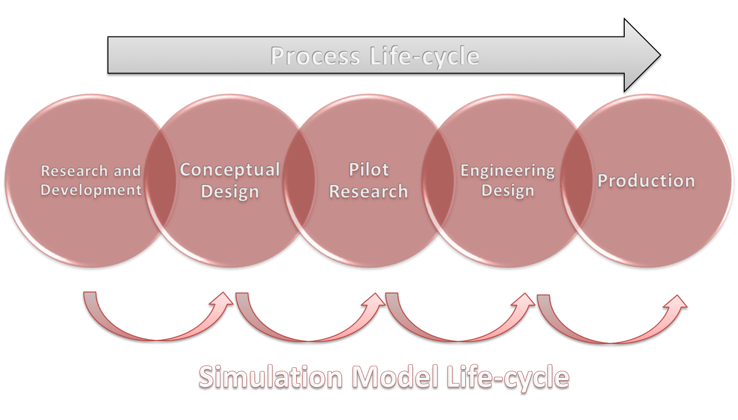
The life-cycle of a chemical compound production or of a chemical process development starts when a new and original idea is advanced taking into account its practical implementation. The former concept with respect to the process lifecycle, which imposed a rigid development from research and development to process operation, has been renewed. It is well known that the most important stages of the life-cycle of a process are:
- research and development,
- conceptual design,
- detailed engineering,
- piloting,
- and operation.
These different steps partially overlap and there is, as well, some feedback between them. For example, plant operation models can be the origin of valuable tips and potential research topics, obviously, these topics directly concern the research and development steps (R&D). The same models, with some changes, are preferably utilized in all the steps. The good transfer of information, knowledge, and ideas is important for successful completion of all the process phases.
The models are an explicit way of describing the knowledge of the process and related phenomena. They provide a systematic approach to the problems in all the stages of the process life-cycle.
In addition, the process of writing the theory as mathematical expressions and codes, reveals the deficiencies with respect to the form and content.
Among the factors that influence the amount of work required to develop a model, we can retain the complexity, the novelty and the particular knowledge related to the process in modeling. Otherwise, commercial modeling software packages are frequently used as an excellent platform.
In the following text, we cover typical simulation models used through the process life-cycle which are shown in the Figure below.
1. Process Modeling Through the Research and Development Stage
The models in the R&D stage can first be simple, and then become more detailed as work proceeds. At this stage, attention has to be focused on the phenomena of phase equilibrium, on the physical properties of the materials, on chemical kinetics as well as on the kinetics of mass and heat transfer.
This action requires careful attention, especially because, at this life-cycle stage, the process could be nothing but an idea.
The work starts with the physical properties, as they act as an input to all other components. The guidelines to choose physical properties, phase equilibrium data, characteristic state equations etc. can be found in the usual literature.
For each studied case, we can choose the level of detail such as the complexity of the equations and the number of parameters. If the literature information on the physical properties is restricted an additional experimental step could be necessary. As far as industrial applications are concerned, the estimation of the reaction kinetics is usually semi-empirical. Therefore, a full and detailed form of kinetics equations is not expected for the majority of the investigated cases. Some physical phenomena along with their effects can require special attention.
The ideal modeling and experimental work have to be realized simultaneously and are strongly related. Models provide a basis to choose, both qualitatively and quantitatively, appropriate experimental conditions. The data obtained from experimental work are used to confirm or reject the theories or the form of equations if an empirical model is being applied. Otherwise, these data are used to estimate the model parameters.
This work is sequential in the sense that starting from an initial guess, the knowledge of the system grows and models get more and more accurate and detailed as the work proceeds.
Based on a good knowledge of the phenomena, valuable tips concerning optimal operating parameters (such as temperature and pressure range as well as restricting phenomena) can be given to the next stages. The degree of detail has to be chosen in order to serve the model usefully.
Practically, the best solution is to describe the most relevant phenomena in a detailed way, whereas the less important ones will be left approximate or in an empirical state.
2. Simulation Models at Conceptual Design Stage
The establishing of the optimal process structure and the best operating conditions characterizes the process development at this stage. Firstly, attention must be focused on the synthesis of the process. The extent to which models can be used in this phase varies. If we have a new process, information from similar cases may not be available at this stage. In the opposite situation, when the chemical components are well known, which usually means that their properties and all related parameters can be found in databanks, the models can be used to quickly check new process ideas. For example, at this stage, for a multiple-component distillation problem, models are used to identify key and non-key components, optimum distillation sequence, the number of ideal stages, the position of feed, etc. At this stage also, we always focus on the full-scale plant. Another question is how the concept will be carried out in the pilot phase. It is known that for this stage, the equipment does not have to be a miniature of the full scale.
The practice has shown that the choices made here affect both investment and operating costs later on. An image of the full-scale plant should also be obtained.
The researchers who work at this level will propose some design computations which are needed by the piloting stage of process life-cycle. Their flow-sheet is the basis of the pilot design or development.
3. Modeling at Pilot Stage
The whole process concept is generally improved in the pilot plant. We can transform this stage into a process analysis made of models if enough experimental data and knowledge about the process exist (for example when we reuse some old processes). For reference, we should mention that other situations are important, such as, for example, knowing that a pilot plant provides relatively easy access to the actual conditions of the process. Some by-pass or small streams could be taken off from the pilot unit and be used in the operation of apparatuses specially designed for the experimental work. Now the models should be ready, except for the correct values of the parameters related to the equipment.
 A special pilot stage feature consists in adding the equations describing the non-ideal process hardware to the model in order to compute efficiency (tray efficiency, heat exchanger efficiency, non-ideality numbers, etc). This stage is strongly limited in time, so, to be efficient, researchers must prepare a careful experimental program. It may be impossible to foresee all the details since the experimentation related to the estimation of parameters is often carried out in sequences, but still, a systematic preparation and organization of the work to be done remains useful.
It is important to remember, that the goal of the pilot stage in terms of modeling is to get a valid mass and energy balance model and to validate the home-made models.
4. Modeling at Detailed Engineering Stage
In this stage, models are used for the purpose for which they have been created: the design and development of a full scale plant which is described in the detailed engineering stage.
On the basis of what has been learned before, the equipment can be scaled-up, taking into consideration pilot phase and related data, as well as the concepts of similitude. Special attention should be paid to the detailed engineering of the possible technical solutions. Depending on their nature, the models can either provide a description of how the system behaves in certain conditions or be used to calculate the detailed geometric measures of the equipment.
For example, we show that all the dimensions of a distillation column can be calculated when we definitively establish the separation requirements. Special consideration should be given to the process of scaling-up because here we must appreciate whether the same phenomena occur identically occur on both scales.
It is useful to have detailed documentation concerning all the assumptions and theories used in the model. The yield and energy consumption of a process are easily optimised using fine-tuned models to design a new unit or process. Depending on the process integration, pinch analysis and other similar analysis procedures can be used to find a solution of heat integration. Various data on streams and energy consumption, which are easily developed from simulation results, can be used to sustain the adopted technical solutions.
5. Modeling at Operating Stage
At this stage of the process life-cycle, the models must include all relevant physical, chemical and mechanical aspects that characterize the process. The model predictions are compared to actual plant measurements and are further tuned to improve the accuracy of the predictions.
This consideration is valuable, especially for the finally adjusted models that create the conditions of use to meet the demand of this operating stage so as to guarantee optimal production. Models can also be used in many ways in order to reduce the operating costs. In the mode of parameter estimation, the model is provided with the process measurement data reflecting the current state of the process, which makes it possible, for example, to monitor the fouling of a plant heat exchanger.
In simulation mode, the performance of the process can be followed. Discrepancies between the model and the process may reveal instrumentation malfunction, problems of maintenance etc.
Verified flowsheet models can be used to further analyze the process operation. In the optimising mode, the models are especially used when different grades of the product are manufactured with the process.
The importance of storing process data has been emphasized here. After all, the data are an important link in the creation cycle of the process knowledge.
Future applications concerning the gathering of new data will provide a powerful tool in the use of the stored data or process memory. It is important to keep in mind that, at this stage, the process could be further improved as new ideas, capacity increasing spin-off projects, R&D projects, etc. are developed. These developments frequently require a partial implementation of the methodology described above.
Therefore, the models of the existing process could act as a tool in further developments. In practice, models are often tailor-made and their use requires expertise. Building interfaces, which take into account the special demands arising from man–computer interaction, can greatly expand the use of the models.
Common Pitfalls of Modeling and Simulation
Discussing Most Commonly Seen Simulation Challenges
24.10.2017.

There are many potential pitfalls that face those who embark on a process simulation development effort. This article discusses some of those most commonly seen.
1. Model only what you understand
It can be said that the utility of a given model is only as good as the degree to which it represents the actual system being modeled. Indeed, a system — whether a process unit or just a section — can only be modeled once it is sufficiently understood. One may ask why modeling and simulation designers develop invalid models? There are many reasons, the first of which is that high fidelity model development requires a significant investment of time and effort. The fact is that many designers are under time constraints to deliver results. Consequently, a careful understanding of the underlying system being modeled and rigorous validation of the model is not always an option.
While understandable, this is at the same time unacceptable. It is highly unlikely that a simulation developer can provide a meaningful result when they did not understand the system they were intending to model. While the timeline might have been met, the result was likely meaningless. Worse yet, the result was likely wrong and might have adversely affected larger design or business decisions. Model only what you understand!
If you don’t have a fundamental understanding of a technology, there is no way you can effectively model or simulate that technology.
This step cannot be skipped in a successful modeling and simulation effort. If this step cannot be completed, it is better to not proceed down the path of modeling and simulation development.
2. Understand your model
It is imperative that the simulation engineer has a full understanding of the tools being used. Most simulations are likely to have errors — even commercial tools. This is especially the case for new simulation implementations. Sometimes, simulation implementations can make assumptions that may not accurately reflect the exact process performance. So, one must be careful in defining basic simulation assumptions.
If the simulation developer utilizes commercial simulation tools for the implementations, it is imperative to allocate the proper amount of time to closely examine and fully understand what that code is doing and what it is not doing.
There is no better way to lose credibility than to not be able to answer questions about one’s own results.
Understand what you have modeled! There are resources available to help with this, including technical support for commercial tools, online groups and user forums for open source tools.
3. Make your results independently repeatable
The first rule of thumb is having the answer to this question: is my model performing as I expected it to perform?
If the answer is « Yes », then new simulation results can also be compared with results in existing literature using underlying assumptions and parameter conditions. Good checking method is as well using a different simulation tool with same process data and assumptions. Getting results that are very close to each other is definitely good confirmation of your model and confirmation that the model results are independently repeatable!
4. Carefully define modeling and simulation requirements
This is an activity that is too often ignored or given superficial treatment. The authors would argue that simulation engineers all too often rush into a modeling and simulation effort without a clear idea of what they are hoping to accomplish. This is a surefire recipe for failure.
The first step is to clearly understand the results of interest that would be generated by a simulation. Not all simulation tools necessarily lend themselves to the same types of output results, so it is important to clearly define expectations so that tool selection is an informed
process.
The next step is to clearly define the required performance of the simulation to be developed. We will focus on three primary dimensions of performance:
- Cost: The overall investment in resources towards the development and maintenance of the modeling and simulation activity. This includes not only original platform costs, but also development time, upgrade and maintenance costs, and troubleshooting.
- Execution Speed: For a given simulation scenario, how quickly can that simulation complete and provide the desired output results? This is generally governed by software complexity.
- Fidelity: For a given simulation task, how accurately do the simulation’s results reflect the performance of the real system.
Note that these dimensions of performance are often contradictory; not all performance dimensions can be achieved simultaneously. Do you want high fidelity? Then the cost will likely be very high. In general, you should prioritize those three dimensions of performance.
A common pitfall is to begin a modeling and simulation effort with unrealistic expectations. Is it really feasible to model all the process components to every little process detail with high fidelity? Probably not. Is it possible to model the entire process to every little detail with many simplifying assumptions? Probably, but it is unlikely to be useful.
When defining requirements and expectations for a modeling and simulation effort it is recommended to begin by choosing the required fidelity. How accurate result is required? A successful effort will always begin with this question because, without a meaningful degree of fidelity, any model and simulation activity is meaningless.
Once the required fidelity is established, one can then begin placing limitations on simulation capabilities accordingly.
Cost is generally bound by an allocation of resources. So given a known cost constraint and a known fidelity requirement, we can then begin building a conceptual model for the simulation. The target fidelity will mandate the inclusion of particular system characteristics with great detail and inputs with particular degrees of accuracy, and also allow for relaxation on other system details and input accuracy.
Note that this exercise requires a strong understanding of the system being modeled and on the underlying concepts.
Remember, model only what you understand!
5. Model what you need and no more
One of the first decisions that the simulation developer must face is to determine what he or she is attempting to demonstrate through simulation and what is the most simplistic model that captures all necessary components. The engineering tradeoff is that increased detail can provide higher fidelity output from the model, but at the cost of complexity — potentially introducing error and certainly increasing debugging time and execution time.
The designer must also realize that a model is always an abstraction from the real world.
Regardless of the level of detail included, a simulation will always be an approximation of the real system; an arbitrarily high degree of fidelity is generally not possible. Also, the cost of increased fidelity at some point becomes greater than the marginal utility of the additional fidelity.
How much detail is sufficient in a simulation to capture the essence of the real world process being modeled? Unfortunately, the answer to this question is that it depends on the particular simulation scenario. The simulation engineer should first decide exactly what is the problem that he or she seeks to address through simulation. What are the inputs and the outputs of the model? Some outputs may be independent of specific details in the model, while others may be correlated and therefore seriously affected if those components are abstracted.
 Simulation always takes the form of an abstraction of a system to allow the designer to gain some insight from investigating various operating scenarios of the system. Yet in other cases, the researcher desires to investigate a process reaction to a single condition that may be unlikely to occur in real life. Perhaps testing the actual system under this condition could be harmful and simulation is the only way to examine the problem. The next step is to decide how much of the system must be implemented for the simulation results to be valid. Ultimately, the simulation engineer is going to have to decide the level of detail required in his or her simulation.
First, the developer must consider the engineering tradeoffs between adding more detail to a model and increased computational time, increased complexity, and increased debugging time.
A more abstract approach that focuses only on the basic behavior of a process is generally very flexible, easier to debug, and has a shorter execution time. But, it may not capture the behavior of interest.
Some Observations on the Practical Use of Modeling and Simulation
Trends in Application of Mathematical Modeling and Simulation in Industry, Research and Innovation
12.10.2017.

The advances in basic knowledge and model-based process engineering methodologies are resulting with an increasing demand for models. The observations given here are commentaries and considerations about some aspects of modeling with the focus on:
- reliability of models and simulations,
- role of the industry as final user of modeling and simulation research,
- role of modeling and simulation in innovations,
- role of modeling in technology transfer and knowledge management,
- role of the universities in modeling and simulation development.
Reliability of Models and Simulations
Correctness, reliability and applicability of models are very important. For most engineering purposes, the models must have a broad range of applicability and they must be validated. If the models are not based on these principles, their range of applicability is usually very narrow, and they cannot be extrapolated. In many modeling and simulation applications in the process industry, kinetic data and thermodynamic property methods are the most likely sources of error. Errors often occur when and because the models are used outside the scope of their applicability. With the advent and availability of cheap computer power, process modeling has increased in sophistication, and has, at the same time, come within the reach of people who previously were deterred by complex mathematics and computer programming.
Simulators are usually made of a huge number of models, and the user has to choose the right ones for the desired purpose. Making correct calculations is not usually trivial and requires a certain amount of expertise, training, process engineering background and knowledge of sometimes very complex phenomena.
The problem with commercial simulators is that, since the simulations can be carried out fairly easily, choosing the wrong models can also be quite easy. Choosing a bad model can result in totally incorrect results. Moreover, with commercial simulators, there is no access to the source code and the user cannot be sure that the calculations are made correctly. The existing commercial flowsheeting packages are very comprehensive and efficient, but the possibility of misuse and misinterpretation of simulation results is high. In CFD and molecular modeling,
the results are often only qualitative. The methods can still be useful, since the results are applied to pre-screen the possible experiments, the synthesis routes and to visualize a particular phenomenon.
The Role of Industry as Final User of Modelling and Simulation
This role is not clear, except in the cases of big companies which have their own research and development divisions. In this case, the R&D company division has specialized teams for modeling and simulation implementation. The properly developed models and simulators are then frequently used, as we have already shown, during the life-cycle of all the particular processes or fabrications that give the company its profile. At the same time, each big company’s R&D division can be an important vendor of professional software.
 The small companies that are highly specialized in modeling and simulation, operate as independent software creators and vendors for one or more company’s R&D division. The use of modeling and simulation in small and medium size manufacturing companies is quite limited. Since small manufacturing companies and university researchers do not cooperate much, awareness and knowledge about modern Computer Aided Process Engineering tools are also limited. There are of course exceptions among manufacturing companies. Some small and medium size engineering and consulting companies are active users of modeling and simulation tools, which allows them to better justify the solutions they propose to their clients.
Modeling and Simulation in Innovations
Modeling and simulation are usually regarded as support tools in innovative work. They allow fast and easy testing of innovations.
The use of simulators also builds a good basis for understanding complex phenomena and their interactions.
In addition, it also builds a good basis for innovative thinking. It is indeed quite important to understand what the simulators really do and what the limitations of the models are. As a consequence, access to source codes is the key to the innovative use of models and simulators. Many commercial programs are usually stuck in old thinking and well-established models, and then, the in-house-made simulators are quite often better innovative tools.
Molecular modeling can be used, for example, in screening potential drug molecules or synthesis methods in order to reduce their number. The existing molecular modeling technology is already so good that there are real benefits in using it. Molecular modeling can be a very efficient and invaluable innovative tool for the industry. The terms “artificial intelligence” and “expert systems” are based on existing knowledge. The computers are not creative, which means that these tools cannot be innovative. However, they can be used as tools in innovative development work. While most of the modeling and simulation methods are just tools, in innovative work, process synthesis can be regarded as an innovation generator, i.e. it can find novel solutions by itself.
Role of Modelling in Technology Transfer and Knowledge Management
Models are not only made for specific problem solving. They are also important as databases and knowledge management or technology transfer tools. For example, an in-house-made flowsheet simulator is typically a huge set of models containing the most important unit operation models, reactor models, physical property models, thermodynamics models and solver models from the literature as well as the models developed in the company over the years or even decades. Ideally, an inhouse-made simulator is a well-organized and well-documented historical database of models and data. A model is also a technology transfer tool through process development and process life cycle. The problem is that the models developed in earlier stages are no longer used in manufacturing. The people in charge of control write simple models for control purposes and the useful models from earlier stages are simply forgotten. Ideally, the models developed in earlier stages should be used and evaluated in manufacturing, and they should provide information to the research stage conceptual design stage and detailed design stage. One reason for “forgetting” the model during the process life cycle is that the simulators are not integrated. Different tools are used in each process life cycle stage. However, simulators with integrated steady-state simulation, dynamic simulation and control and operator-training tools are already being developed.
The problem is that the manufacturing people are not always willing to use the models, even though the advantages are clear and the models are made very easy to use.
Role of the Universities in Modelling and Simulation Development
The importance of modeling and simulation for industrial use is generally promoted, in each factory, by the youngest engineers. The importance of computer-aided tools to the factory level is best understood when the application of modeling and simulation has a history. The importance of modeling and simulation is not understood so well in the sectors that do not use computer-aided tools.
Technical universities have a key role in the education of engineers as well as in research and development. In fact, the universities’ education role is absolutely fundamental for the future development of the industry.
Indeed, in the future, the work of a process engineer will be more and more concerned with modeling and computation. Moreover, the work will be all the more demanding so that process engineers will need to have an enormous amount of knowledge not only of physics and chemistry, but also of numerical computation, modeling and programming.
Reference: T.G.Dobre, J.S.Marcano: Chemical Engineering: Modeling, Simulation and Similitude
Process simulation as the key discipline of chemical engineering
Application of process simulation in disciplines of chemical processing
19.08.2017.

Chemical engineering can be defined from many different aspects. However, all the scientists and professionals agree that the process is the center of it. To make a distinction from any other discipline, the role of chemical engineering could be defined with its purpose to develop, design, construct, control, optimize and manage any process involving physical and/or chemical changes and make this process profitable without violating environmental balance.
Process simulation as discipline uses mathematical models as basis for analysis, prediction, testing, detection of a process behavior unrelated to whether the process is existing in reality or not. Process simulation is there to increase the level of knowledge for a particular process and chemical engineering in general.
So, when those two concepts are put together, we can look into the chemical engineering as a discipline defining how the process should be developed and simulation as the tool helping us to explore the options. Chemical engineering needs to know how the process should be designed while chemical engineers use the simulation to explore all the process design options and define the optimal one.
Process simulation is today applied in almost all disciplines of chemical engineering and engineering in general. It is the inevitable part of disciplines from process design, research and development, production planning, optimization, training and education to decision-making which makes it one of the most important disciplines of engineering. A wide palette of simulation solutions is mentioned below.

Process design
Process design represents one of the traditional applications of mathematical modeling and simulation. Process synthesis and process design use steady state models to define process flowsheet accompanied with material and heat balance. The objectives of process design are to find the best process flowsheet and optimum design conditions. This can be a complex task which needs to explore great number of options and is not possible without the usage of mathematical models and process simulation.
Research and development
Chemical engineering is like a fountain of challenges producing a continuous inspiration for researchers on their projects. No research project is possible without certain amount of mathematical modeling and process simulation involved. Thus, it can minimize the amount of experimental research. There are certain parts of the process which continuously need evaluation and improvement. Reactor sections are very often that particular part of the process, especially if the catalyst is involved in the reactions. For this purposes, continuous monitoring of performance is done in order to change reactor’s conditions at the proper time. Engineers working with research and development are involved with detailed mathematical models which include a huge number of physical and thermodynamic properties to help them evaluate current or improved process conditions.
Production planning
Production planning and scheduling accompanied with economic calculations represent important discipline which is placing a chemical process or industry on the market. Ones the process is running, its profitability becomes one of the most important tasks for a chemical engineer. Process profitability is explored and defined through production planning and scheduling models which are used to provide the answers to the questions how to define optimal production and operation.
Change of market, change in feeds and products need constant evaluation in order to guarantee profitability. Mathematical models are used for simulation of all the possibilities as the guidance on the way to the optimum solution. This is done in order to help management to make the right decisions.
Dynamic simulation
Dynamic simulation is analyzing an optimal process operation, safety, environmental constraints and controllability to help define control strategies, goals and control parameters.
Dynamic simulation is first used during process design phase to help define control strategies. When the process is in operation, it is used to analyze, test and optimize operating conditions. This type of analysis can give answers about process bottlenecks and how to resolve them. Because the „time“ as a variable is included, dynamic simulation is focusing on the problems of control that steady state simulation cannot comprehend.
Training and education
Simulation is of great support to enable training and education of engineers and operators. It is present in the form of the Operator Training Simulator. As education of operators and engineers is becoming more and more important challenge due to modern and more complex technologies, OTS is the powerful learning tool which enables natural feeling of a process control in the virtual reality. Training of defined scenarios, process start-up and shut-down is representing the enormous impact on process safety and competence of operators to be able to handle unexpected conditions. It is also giving them more knowledge to deal with daily operation challenges.
Optimization
Dynamic models are enabling chemical engineers to continuously run the unit with defined optimization strategy, having the process knowledge transformed in the shape of the mathematical model hidden inside the control algorithm, called Advanced Process Control (APC). This approach is giving engineers and operators the ability and operators to almost run the unit such as operating the plane on auto pilot, constantly taking care of economical benefits.
Decision-making
Decision-making process supported by different kinds of calculations, models and simulations is far more efficient one than the one built on assumptions. There is a whole formulation of how different models can support the decision-making process to make it less exasperating and difficult.
In conclusion, the short survey about process simulation is giving us a message: there is almost no discipline of chemical engineering that can afford to ignore the importance of process simulation. It is the inevitable part of chemical engineering and engineering in general. Process simulation is like a flashlight in the hands of a chemical engineer guiding one to the best engineering solution.
Thermodynamic basics for process modeling
Basic guidance to help you avoid problems caused by selection of wrong thermodynamic model
Ivana Lukec 27.08.2015.

The story about thermodynamics can hardly be a simple one. If it somehow could be a simple one and the world would be ideal – we would have only one nice equation that is good enough to describe any system. But in the unideal world, things are far from that. When developing a process model, a chemical engineer should have enough knowledge to be able to choose from a large number of thermodynamic systems. Chemical engineering as a field is progressing day by day and as a result of that the number of thermodynamic equations and parameters is increasing too with the aim to improve mathematical descriptions of different systems. With more complex thermodynamic systems, there comes a joint problem of more and more challenging mathematical operations. So, our knowledge becomes very important in selecting the most appropriate thermodynamics package. We will try to give some simple and practical instructions through this highly complex field of chemical engineering and process simulation.
Why do we need thermodynamics?
But, let’s go from the beginning… why do we need to know thermodynamics at all to be able to perform a simulation?
Well, in some cases, we don’t necessarily do… at least we don’t necessarily have to know all the details, but we have to be aware of it. We don’t need to know all that’s behind in cases we are performing a simulation based on a large number of data sets and are using their relationships to build the model. In this case we are not looking into details of the system, only using the data to build the model. Examples are applications of artificial neural networks, linear regression etc. However, when talking about process simulation, most of the time we do refer to rigorous models and simulation tools, such as Hysys, Chemcad, Pro II etc. This approach is based on traditional chemical engineering laws and thermodynamics represent the essence of it. Therefore, when building a model in any process simulator, we need to make a selection of the proper thermodynamic system.
Some simple & practical instructions are defined to help you through the selection and minimize the possibility of problems.
One thing to have in mind: taking the wrong way while developing a process model can cause a huge waste of time and misleading results. So, try to be careful!
Thermodynamics finds its origin in experience and experiment, from which are formulated a few major postulates that form the foundation of the subject. Among those are 1st and the 2nd law of thermodynamics, the definition of enthalpy, entropy, equilibrium etc.
Selection of the appropriate thermodynamic package is one of the first steps when building the mathematical model. It is also one of the most important steps because a simple click of a mouse in most of the simulation programs will have the critical impact on simulation results. We might even not get the results.
The choice of a thermodynamic package will have an impact on:
- Accuracy of results,
- Complexity of the calculation,
- Convergence.
What is the thermodynamics actually defining?
Thermodynamic packages consist of different sets of data and equations systems which represent a group of methods to perform all necessary thermodynamic calculations. Thermodynamic packages consist of all chemical and physical component properties together with different thermodynamic models which are applicable for different systems dependent on components and working conditions of the process (pressure, temperature). Most known are Soave-Redlich-Kwong, Peng-Robinson, Lee Kesler etc. It is our task to select one of them when building a model.
Also, it has to be noted that most applications require only one set, but complex flowsheets may be modeled best with several.
Step 1: Keeping the right way: overview of the process to be modeled
Overview of the modeled process refers to a review of the component list and expected working conditions: are components liquids or gasses, are they mostly hydrocarbons, is there any specific components such as H2S for example etc. When looking into temperature and pressure characteristics, it should be noted if the expected temperatures and pressures are around atmospheric or are they significantly higher. Some simulation programs may suggest what thermodynamic system suits best for a defined component list. However, it is always good to review the default selection. If there is no any suggestion or we don’t want to follow it, then we should follow some general guidance based on our system definition and components list.
Step 2: Selecting the thermodynamic model
Some of the most important thermodynamic models are:
- Peng-Robinson – a thermodynamic model ideal for vapour-liquid calculations as well as calculating liquid densities for hydrocarbon systems. Generally not useful for highly non-ideal systems.
- Sour or modified Peng-Robinson – modification of Peng-Robinson model to extend its range of applicability to highly non-ideal systems.
- Lee Kesler Plocker – a model is the most accurate general method for non-polar substances and mixtures. It is most often used for light hydrocarbons and for reformer systems containing high quantities of hydrogen.
- Soave Redlich Kwong – in many cases, it provides comparable results to Peng-Robinson model, but its range of application is significantly more limited. It is most often used in gas and refining processes. Generally not useful for highly non-ideal systems.
- Sour or modified Soave-Redlich-Kwong – modification of Soave-Redlich-Kwong model to extend its range of applicability to highly non-ideal systems.
- NRTL – generally used for non-ideal liquid applications when calculating phase behavior (vapor-to-liquid or liquid-to-liquid equilibria).
- UNIQUAC – generally used for non-ideal liquid applications when calculating phase behavior (vapor-to-liquid or liquid-to-liquid equilibrium).
- Wilson – generally useful for slightly non-ideal applications.
- Braun K10 – It is generally useful for heavy refinery hydrocarbons at low pressures.
- Ideal – These methods should be used with pure component streams and streams with very similar components and for pressure around atmospheric pressure.
The table summarizes the priorities when choosing the thermodynamic model. The best selection is defined with « 1 », a little bit less appropriate but still possible with « 2 » and so on. Attention should be paid on operating pressure.

Step 3: Continue with model development
Upon the selection of the thermodynamic model, you can continue your work. In case you are facing any problems related to model accuracy or convergence, save your work, do another copy of your simulation and try to use another thermodynamic model for your simulation.
Selecting the proper thermodynamics can be a challenge many times, especially while modelling more complex process or a process with many different types of components. Use this information as a general guidance and in case of facing difficulties, you can refer to some of the following books:
J.M. Smith, H.C. Van Ness, M.M. Abbott: Introduction to Chemical Engineering Thermodynamics
P. K. Nag: Basic and Applied Thermodynamics
Models and reality
How mathematical models are employed in industrial practice
Ivana Lukec 02.08.2015.

What is a „mathematical model“?
What does the term of „mathematical model“ represent in chemical engineering and engineering in general? A broad definition is: a model is a „virtual version of reality“. In literature, there can be found definitions such as « an image of reality from a particular viewpoint ». Or a more precise one: A model is a simplified representation of those aspects of an actual process that are being investigated (Kafarov & Kuznetsov 1976). A mathematical model of a real chemical process is a mathematical description combining experimental facts and establishing relationships between the process variables (Babu).
Definitions are differing almost as the models: in viewpoint, in the level of details and in the goal of development.
Model in practice
From practical point of view, these 3 points are important to have in mind while developing a model and analyzing the relationship between the model and the reality:
- Model always has a certain deviation from the real process,
- Definition of the model and a mathematical tool is dependent on the problem it is exploring,
- Characteristics of the model are dependent on the engineers who work on the development: the level of their knowledge, their experience and their vision of the reality.
There is no way that two people who work independently could develop the model which would look the same and function the same, no matter what tool they would use. As we perceive the colors differently, every person looks into a problem differently with the different knowledge level and different previous experience and it is inevitable that the developed model is different too.
When developing a model of a particular operation, such as a distillation column, the different approach is employed when model is developed with the purpose to define the sizing parameters of the column or when the column has to be analyzed to explore the control strategy or product quality. Dependent on the purpose, different mathematical method and different level of details have to be applied.
Answer these questions before building the mathematical model
Preparation for any project that involves the process simulation and employment of process models requires answers to these questions:
- Define the system and define the modeling subject: what operations and process equipment need to be included for modeling, define the system boundaries,
- What is the goal of the model? Is it process design? Is it optimization? Is it analysis of control strategy? Is it training? Is it safety? Etc… Answers to this questions can help you to define the level of modeling details and with it, the model complexity,
- What data need to be known for a defined system and purpose and are all those data available? Often, this is the point where certain assumptions have to be made with clear awareness that those are not in the conflict with defined goal of the model
- What software tools are needed to complete the task? Is it only a programming tool needed or a professional process simulator? Is it available or does it mean a new cost? Is this expensive or affordable and are there any free tools to complete the task?
Accuracy
Dependant on the model type, the simulation tool and adequacy of the data – one can build more or less accurate model. It will never be a 100% accurate. So to say: a perfect model doesn’t exist, but having one that is close enough can be of a lot of help and a problem solution.
Is it a model then an art of science? In a way, it can be accepted as a creative perspective of science and engineering. It’s purpose is to solve, but to solve a problem one can use different approaches towards the solution and be as creative as possible.
The model is corresponding to reality through the flowsheets, P&I diagrams, and all the data.The model needs to take into account properties of all the materials and other physical characteristics defined by temperature, flows, pressures and composition.
However, the value of a good model is often priceless.
A good model
A good model should reflect the important factors affecting a process and must not be crowded with minor, secondary factors that will complicate the mathematical analysis and might render the investigation difficult to evaluate. Depending on the process under investigation, a mathematical model may be a system of algebraic or differential equations or a mixture of both. It is important that the model should also represent with sufficient accuracy both quantitative and qualitative properties.
Application of models
Models are used for a variety of applications, such as the study of the dynamic behavior, process design, model-based control, optimization, controllability study, operator training, and prediction. These models are usually based on physical fundamentals, conservation balances, and additional equations.
Welcome to SimulateLive.com
A welcome note for our readers
Ivana Lukec 18.08.2015

Dear readers,
Welcome to SimulateLive.com and thank you for visiting!
SimulateLive.com is a professional portal for the promotion of process modeling, simulation, and related engineering disciplines with the aim to serve process industry.
Because process simulation has become one of the most important disciplines of process industry with globally growing market, the aim of this portal is to bring it closer to engineers and industry, connect the vendors and the community it serves via the web-site, e-newsletters, social networking, written and video lessons, demonstrations, product reviews, events and other digital media offerings.
We will be promoting knowledge and induce communication among the professionals on subjects related to process simulation, operator training simulators and trainings, process design and optimization, advanced process control and real time optimization, process analysis and monitoring.
We are here to serve you! You are very welcome to give us your feedback, let us know what are topics of your interest, what are the products and vendors of your interest and to share with us your stories! Our engineering and editorial team will do their best to provide support.
Our editorial team mission is to serve the information needs of engineering, operations and management personnel whose job it is to simulate, design, operate, control, monitor and optimize the process units. Engineering design companies and software solution vendors which play an important role will be represented and their products reviewed by highly skilled engineering teams. Our vision is to provide space to present industrial solutions, discuss operational problems and learn from other people’s experience.
Process simulation and plant safety
How Dynamic Simulation Can Be Employed to Help Managing Safety Issues
05.11.2017.
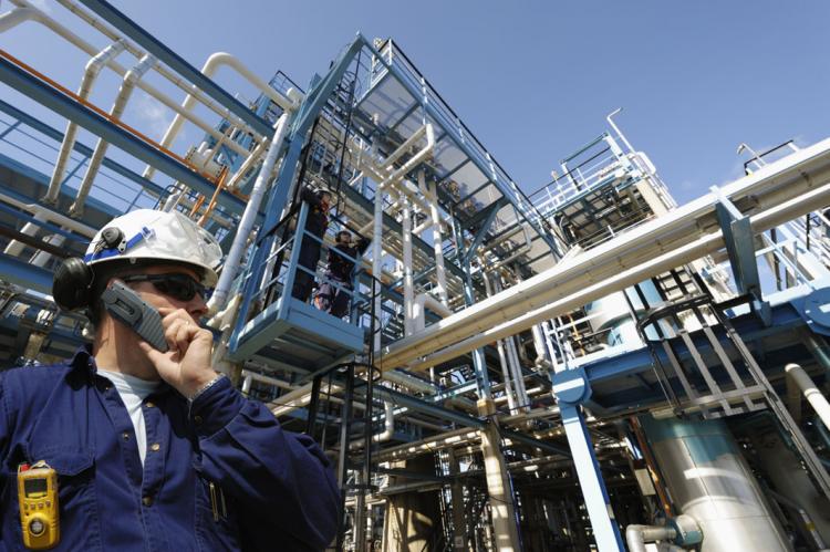
The safety of industrial plants is the most important concern of everyone related to the process industry. Accidents in chemical plants make headline news, especially when there is loss of life, or the general public is affected in the slightest way. To prevent any possibility that lives of people or property are put to danger, each company is expected to develop and enforce its own practices in the design, installation, testing, and maintenance of safety systems and procedures. Also, the general guidance and documents are produced by governments, industrial groups, and professionals.
Process control and safety
The progress of automation over the last decade and installation of most developed control systems resulted in significantly improved safety environment. When automated procedures replace manual procedures for routine operations, the probability of human errors leading to hazardous situations is lowered. The enhanced capability for presenting information to the process operators in a timely manner and in the most meaningful form increases the operator’s awareness of current conditions in the process. Moreover, as operator training simulators are gaining more and more attention from industry professionals and management, their contribution in improving operators’ level of knowledge and readiness to handle all dangerous scenarios has become enormous.

By looking into a typical industrial unit, process safety can be divided into a few levels. As shown on the picture, process design is representing the core. It is representing all included chemicals, all operating conditions and technological procedures for normal operation, start-ups and shut-downs. Control and safety systems are applied based on process characteristics and technology defined by process design. Physical protection is the last point of defense and should be directed by the procedures and standards defined for the particular unit or section.
How a dynamic simulation contributes to keeping the plants safe
Dynamic simulation is very important in gaining the knowledge about process safety for all mentioned safety topics and can be applied from two different aspects:
- Operator training system (OTS),
- General dynamic simulation.
Certainly, application of OTS has the invaluable role in exploring, analyzing and training of process safety.
Original process design in a form of a mathematical model is connected to original control and safety system to represent the original unit in virtual reality.
Therefore, operators and engineers can train all hazardous situations of their original unit on a daily basis. Moreover, engineers can test and evaluate control strategies of original control and safety system. Also, skills of operators for handling dangerous scenarios can be evaluated.
However, OTS systems are quite expensive and the cost of their implementation cannot always be justified.
But, dynamic simulation can still enhance to level of knowledge and therefore the level of safety during unexpected situations through application of a general dynamic simulation, as can be done using simulation software such as Hysys, Dynsim, Chemcad etc.
The key difference between general dynamic simulation and OTS is that general dynamic simulation will not be connected to original control and safety system; instead, it will be defined in a more general way. It can be replicated to some extent, dependent on the simulation software used, its definitions of process control elements and depth of the user definitions.
So, general dynamic simulation cannot be used to test and analyze the behavior of a control system but it can be used to test, analyze, explore and learn about all safety issues related to process design, processed chemicals, technological characteristics and procedures of the unit.
Behavior and interaction of process variables in the cases of hazardous situations and operating conditions which are far from steady state can be explored to upgrade overall safety condition of the unit.
Examples of scenarios which can be analyzed using general dynamic simulation
When new plants are built, operating and safety procedures related to process design and technology are usually produced by the licensor. However, this might not be always the case and moreover, this type of documentation most often does not exist for older plant.
Therefore, procedures and facts that can be produced from performing dynamic simulation tests should be implemented into overall safety procedures of a particular unit.
Typical examples which can be explored using dynamic simulation and can significantly contribute to internal level of knowledge and standard procedures are:
- Failure of the feed pump: for many chemical, refining and petrochemical processes, this is a dangerous situation, especially if there is a heater or reactor one of the first downstream process units. With this exercise performed using a dynamic simulation tool, behaviors of all downstream process operations is explored, all consequences can be explored and caution measures defined
- Shortage of one reaction component: similar as for the previous example: usually the loss of one reactant of the reaction can cause a dangerous situation. Dynamic simulation should be used to evaluate danger, analyze possible consequences and define caution measures
- Failure of cooling water: loss of the ability for cooling is serious safety issues which can have influence on reactor operation, columns operation and cause serious uncontrolled temperature increase. With dynamic simulation, all risky spots are identified. So that standard procedures can be checked, evaluated and complemented.
- Dynamic simulation as the tool for improving safety standards will be applied in a similar way for the cases of:
- Entrance of the unexpected component in feed stream,
- Catalyst deactivation,
- Shortage of one reaction component,
- Failure of cooling water.
Being able to predict all the possible risks is already a halfway to maintaining the safety of industrial plants. Dynamic simulation has an important role in estimating possible consequences and describing the incident outcome. This knowledge should be used to evaluate and continuously improve safety standards and procedures to keep safe impacts on people, environment, and property.
Dynamic Simulation and Chemical Engineering
Application of Dynamic Simulation
27.09.2017.

Unsteady-state or dynamic simulation accounts for process transients, from an initial state to a final state. Dynamic models for complex chemical processes typically consist of large systems of ordinary differential equations and algebraic equations. Therefore, dynamic process simulation is computationally intensive.
Dynamic simulation is most often used for: batch process design and development, control strategy development, control system check-out, the optimization of plant operations, process reliability/availability/safety studies, process improvement, process start-up and shutdown.
What Makes Dynamic Simulation So Important
For the typical case of a process industry, we model the plant subunits and their regulatory control. The relevant equations are solved repeatedly in the time domain and the values of temperature, pressure, flow and composition as well as the valve openings and the process control system output are calculated at every point of interest. Thus, the interactions between the process subunits can become obvious. Further, the process reaction to disturbances (such as feed variation, instruments failure or change of operation strategy) can be fully investigated.

As the industrial process units are becoming increasingly complex with applications of new technologies that include thermal integration, modern process design and advanced process control systems. The units are required to operate non-stop for longer periods of time at optimal conditions. The need for flexibility, regarding processes or equipment, continuously increases. It is, further, well known that big and fast changes in the plant operating conditions should be avoided, since the effects of moving from one operational region to another can be unanticipated and possibly dangerous. Thus, one needs to be aware of the danger zones and when these occur. In brief, the behavior of the process unit on the whole is not a simple sum of the plant’s subunits actions.
Safety, environmental, and economic factors highlight the importance of understanding the design and operating of the plant, as well as the sufficient training of the plant personnel at a time of an ever-increasing worldwide need for highly qualified and capable operators.
Dynamic simulation is the only economically effective solution to these needs, since it yields a lot more information than what traditional steady state simulation offers. This is because dynamic simulation allows us to study a plant’s behavior in a wide range of operation conditions, like during start-up or shutdown or during emergency situations.
Further, it can incorporate algorithms describing the process unit safety or regulatory control philosophy. Thus, it is possible to use a dynamic model for the investigation and improved understanding of the unit’s behavior based on design or operational data.
Applications of Dynamic Simulation
The dynamic simulation applications in the process industry can be used for a variety of purposes. These include:
- Operator Training Simulators
- Operation Optimization
- Modification of Process and Control System Design
- Investigation of Operational Issues
- Safety and Environmental Issues
Operator Training Simulators
In today’s world, when industry is facing problems of massive retirements of their work force and a skills shortage, dynamic process models integrated with the plant’s Distributed Control Systems (DCS) can be used to capture, maintain and develop existing operating skills. Among others, a fully deployed operator training system can be used to:
- Offer plant operators an improved understanding of the unit operation and handling.
- Familiarize the operators to the process design and the control systems, while emphasizing the interactions between the two.
- Demonstrate the use and explain the advantages of advanced process control.
- Control and verify the operators’ actions.
- Practice without the presence of an instructor.
Operation Optimization
A dynamic model of a process unit can be used to optimize operations. Some typical examples
are:
- Creating, testing and verifying procedures for the safe start-up and shutdown of the process or for the minimization of time that plant equipment stays out of operation.
- Finding ways to move the plant operation to equally feasible and safe but more profitable conditions.
- Addition of new process lines, before or after start up, for improved plant controllability during transients.
Modification of Process and Control System Design
The process design can be relatively easily modified and troubleshoot with a dynamic simulator.
- Technical assessment of alternative design solutions.
- Dynamic studies: Analysis of controllability, de-bottlenecking, depressurising, feed differentiation effects etc.
- Determination of characteristic equipment parameters (instrument minimum sampling time or permissible noise levels, controller tuning parameters, control valves characteristics etc.)
- Compressor performance verification and avoiding compressor surge.
- Effects to plant controllability due to equipment modifications.
Investigation of Operational Issues
Use of dynamic simulation is very efficient in finding answers to problematic process behavior and can help a lot to target process challenges such as:
- Rapid assessment of alternative solutions to what-if scenarios.
- Achievement of optimal plant conditions, after an unanticipated change.
- Incident investigation and procedures for future prevention.
- Estimation of functional parameters for instrumentation.
Safety and Environmental Issues
- Exhaustive testing of plant procedures and detection of unfavorable conditions (e.g.explosive/toxic mixtures, formation and deposition of hydrates etc.) due to transients normal functions.
- Verification of depressurising procedures.
- Verification of DCS and emergency shutdown system control loops and sequences.
However, although benefits and importance of dynamic simulations are unquestionable, the use of dynamic simulators is still not standardized to the level of steady state simulation. The problem is that the manufacturing people are not always willing to use the models, even though the advantages are clear.
Making the Most of Life-Cycle Dynamic Simulation, from Concept to OTS and Beyond
Safety, reliability, efficiency, lower costs – what’s not to like?
John Hinsley, Independent consultant in dynamic simulation, flow assurance and process control. 14.11.2016.

Steady state process simulation is universally accepted as an essential tool for project development across the process industries. Every process engineer expects to have easy access to HysysTM or one of its derivatives or competitors for developing process heat and mass balances. Dynamic process simulation, however, is still seen as a “nice to have” by many projects despite the clear benefits it can bring. This is despite the technology having been available for many years to perform high-fidelity dynamic simulation of process facilities and multiphase pipelines, with tremendous improvements in computing speed and ease of use over the last couple of decades.
So what are the benefits of using dynamic simulation, and why is it not being used more routinely?
This article aims to answer these questions, with specific reference to the Upstream Oil & Gas Industry, but close parallels exist in most sectors of the Process Industries.
Dynamic process simulation can provide valuable contributions throughout the project life cycle:
- Coarse assessment models for concept selection – early consideration of operability and process interactions can increase reliability of concept screening and can help avoid problems which would otherwise become increasingly expensive to correct as the development progresses.
- Engineering study models for design development and verification – perhaps the most widespread use of dynamic simulation during the design phases is to focus on “hot spots” such as HIPPS and compression, but identifying and understanding dynamic interactions and operability issues (e.g. rate changes, start-up, responses to failures etc.) can add value throughout the process. It can help to ensure system-wide data coherence, can significantly enhance process control philosophy development, and is unmatched for resolving potential HAZOP actions.
- Well-to-export integrated model for proof of seamless operation of full system – given the necessity to segregate engineering effort, this is by far the best way to reveal and address any integration problems when all sections are connected and thus have realistic dynamic boundary conditions. Ideal tool for developing operating philosophies and procedures, and for demonstrating the full system consequences of design decisions.
- Interfaced models for control system development and testing – a fully dynamic model allows the control system to be tested under very realistic conditions at a tiny fraction of the cost of actual reality (no safety risks, no loss of production). Sufficiently detailed models can allow pre-commissioning tuning of controllers.
- Operator training simulators – long accepted as essential throughout the Process Industries, although too often limited in scope such that operators only learn of interactions with connected systems later, during production – sometimes too late. More effective and less expensive when based on models developed during earlier activities.
- Real-time operator guidance systems (e.g. Pipeline Management Systems) – extremely valuable for predicting conditions where they are not measured, providing “look-ahead” and “what-if” functionality, and helping operators with infrequent operations (e.g. pipeline pigging, re-start after maintenance shut-downs etc.).
- Virtual flow metering – especially valuable for subsea wells, providing back-up for physical meters which are expensive to maintain or replace. Should be considered part of the process instrumentation, with appropriate security and robustness (as opposed to simply an operator guidance tool).
- Engineering model(s) for production support – continued use of dynamic simulation during operation for process modifications, debottlenecking, troubleshooting etc.
To maximize the return on investment in dynamic simulation, the project needs to gain as many of these potential benefits from the most reasonable amount of effort.
Note that this does not mean minimum effort – a judgement is required on the benefits gained from each level of expenditure. This judgement needs to be made in the widest project context, with a firm understanding of the value such work can generate. The benefits of early work are often realised in later design phases (when the contractor may have changed), in training, commissioning, and particularly in production, long after the design contractors have lost interest! This strongly suggests that the Operating Company should take ownership of the dynamic simulation effort throughout the project development.
Starting the dynamic simulation work as early as possible in the project will magnify the value significantly – largely because the less a design has progressed the less it costs to change it.
There is a misconception that it is impossible to start until there is enough firm data available. However it is possible, and very informative, to build models of early concepts using estimated data – often the act of making such estimates is enough to highlight sensitivities within a design, or to indicate which factors will make the biggest difference to operation or production efficiency. Again it is apparent that OpCo ownership of the dynamic simulation is key – guiding the design using its results will be likely to improve the project life-cycle economics, whereas the design contractor may see little or no benefit to their bottom-line.
Once the dynamic simulation effort has started, it makes sense to continue using the same tools (software) and even the same team if possible – providing both costs savings and valuable continuity, carrying the project’s history forward through the design phases and into production.
Too often project decisions are made for reasons which are later forgotten, making them either difficult to challenge or too easy to overturn, depending on the prevalent culture in the organization. Achieving continuity relies on early selection of personnel and software tools, which itself requires a deep understanding of the life-cycle opportunities and the market offerings that can support each stage.
From the outset, the selection of simulation tools should be driven by a vision of the final scope of dynamic modelling, usually set by the need for operators to be trained to understand the process as a whole and its interactions with external systems. The choice should include consideration of the capability of the core process simulation software to integrate models running in other packages – e.g. multiphase pipeline models, or “black-box” models of proprietary technology. Its ability to emulate and interface to a wide range of control systems also needs to be understood in the context of training simulator plans.
The team of engineers chosen to build, run and interpret the simulations are the other vital element which should be given serious attention early in the project. They need experience of the simulation tools, process design, process control and operation, so they are able to correctly and efficiently identify issues and solutions and to work effectively with other engineering disciplines.
Dynamic simulation is often perceived as a specialist discipline – not without some justification – which supports personnel continuity, since they can then also develop into valuable specialists in the project’s process system. Continuous involvement of Operations representatives from the earliest stages also helps maximise the value added by dynamic simulation effort.
When managing dynamic simulation as part of a project development, it is vital to understand the investigative nature of the activity. It is possible to have a rough idea in advance of the most likely issues that need modelling, but it will never be possible to predict all the problems that may be identified during building, commissioning and using a model to support the design effort. If the use of the model is limited to a very strict, predefined scope and schedule, then many opportunities for improving the process design will be missed.
Dynamic simulation is by necessity detailed and comprehensive, and as such is an ideal way to find the “unknown unknowns” during design phases. But this can only happen if the project management and the contract structure allow sufficient freedom to appropriately experienced simulation engineers.
The above scenario requires a rethink to the typical contract strategy for dynamic simulation. Most projects include it in the scope of the FEED and EPCIC contractors who insist on fixed (minimal) scopes of work and then treat it as a cost (and a nuisance – particularly if it finds anything wrong with their design!). The first complete system model is often left to the Operator Training Simulator, which is bundled into the Main Automation Contractor’s scope, for whom the sale of extra hardware is more interesting than spending time building a high quality dynamic model. This approach provides no motivation for the simulation work to be used as a vehicle for value improvement throughout the project, nor is there any opportunity for Operations to influence its use or to use its results to influence the design. Together with segmentation of effort between numerous contractors and suppliers, this tends to diminish the value gained from dynamic simulation, giving a false impression that it is an expensive luxury.

An alternative contracting strategy that addresses these issues, would be for the Operating Company to commission the dynamic simulation effort directly, integrating it into the their own project technical team. This should begin in Concept Selection, with the model(s) evolving and increasing in scope throughout the design phases. Typical contract practice requires data and drawings to be provided to the Operating Company as they become available, which allows estimated data to be gradually replaced and received data to be verified. If this is brought under an « integration management » umbrella it becomes a tool for focusing the design effort on overall system performance and operability, as well as helping check each element of the system as the design crystallizes. The detailed design contract would stipulate that models of any proprietary process units should be provided as « black boxes » suitable for integration into the full model. The Operating Company’s model can be used by their Technical Assurance team to verify the contractor’s design or to highlight areas where it can be improved. Engendering a spirit of cooperation between the OpCo and Contractor is the key to maximizing value from this strategy – carefully designed production performance incentives can help.
By the end of detailed design the model should have been thoroughly tested and widely used, making it an ideal basis for control system testing and for the Operator Training Simulator.
For continuity, it makes sense for the OpCo’s team to complete the scope of model – it needs to include the full system for which the operators will be responsible, including any external influence on how the process is operated (e.g. wells, pipelines, utilities). The full model would then be free-issued to the OTS vendor (usually the control system vendor) for integration into their system. This approach reduces costs, schedule and risks to the project, and has the advantage that the Operations representatives will already have had a chance to influence the scope of the training tools.
As alluded to above, to get the best value from dynamic simulation in early phases requires upfront planning. It is important to gain an early understanding of how the choice of software tools for each phase will affect costs and benefits later.
In general it is not necessary to use the same software vendor/package for dynamic simulation as that being used for steady state (H&MB) design work. This is for two reasons: firstly there is significant effort involved in building a good dynamic model, even when starting from a steady state model in nominally the same package, due to the orders of magnitude increase in input data and process detail required. Secondly, using the same software for both activities could actually hide systematic or common errors (e.g. in the fluid properties models).

I saw a particularly severe example on a project where the H&MB simulation had been performed without correcting the water density from the standard equation of state (resulting in a 20% error!). Since this was a simple mistake in the setup of the fluids model, it was common to the dynamic version. Such a large error was easy to see when checking the model output (which raises the question “why didn’t the contractor notice?”) but more subtle errors can go unnoticed without using different software as an independent verification tool.
Once a dynamic model of significant size has been built for the project the advantages of continuing with the same software will become apparent. At each stage the savings increase as the model becomes larger and more detailed, to the extent that it can be possible to justify a detailed engineering study model almost entirely by the cost savings from passing on the resulting model as the basis for control system testing and the training simulator. A project I worked on some years ago in the North Sea tried to save money by allowing compressor vendors to provide their own controllers. The model we developed for engineering studies was later used to test these controllers – both by emulation and simulation (hardwiring to the actual controllers) – finding and fixing enough faults to pay for the entire simulation effort many times over. This example also indicates the difficulties with estimating benefits of dynamic simulation.
When the problems are solved before commissioning, no one notices as there is no fault condition with which to compare the smooth operation – so no one says “that finding saved us $Xm”.
Likewise, many unsolved problems cause “mysterious” trips or maybe just reduce production efficiency – which, during production, may be impossible to connect with a cause that could have been avoided by better use of dynamic simulation. Of course, having access to the full engineering model during production can help troubleshoot such problems.
Usually, real-time simulation tools will also benefit from the “software continuity” rule, with the possible exception of Virtual Flow Metering. For use with remote wells (especially subsea) the scope of the model for each VFM is relatively small (usually the well bore and Xmas tree, including the choke valve) and may need to be modelled in more detail than would usually be required for study and training purposes. Hence the other requirements for VFM may override the savings from using an existing model – VFM offerings vary widely in their approaches and capabilities, so it is vital to make the right choice for the specific characteristics of the project.
Much of the above advice for extracting value from established process engineering tools may seem straight forward, but it is still not the norm.
So what are the reasons why dynamic simulation is still not routinely used on all projects? I have already mentioned the perceptions that it is too expensive (which relates to the difficulty in quantifying the benefits), that it needs specialists (who may be difficult to find), that is takes longer and is difficult to predict (and hence to schedule) and, falsely, that it needs too much data to be useful early in a project.
The current typical contract strategy reinforces and compounds these attitudes – often making dynamic simulation an irritation for the contractor, rather than an integral part of their team. Delegating the simulation effort to the design contractor usually reduces the life-cycle benefits, with the same model being less likely to be used during training or production. Without the OpCo taking control of the dynamic simulation, segmented supply leads to segmented modelling efforts – increasing costs but reducing benefits.
The knowledge gap, particularly within Project Management, creates a Catch-22: until dynamic simulation is used more, the understanding of the potential benefits will not be widespread enough to realise the full value, but without seeing the benefits delivered, it won’t get used enough…
Breaking this cycle will need OpCo managers with vision and courage to seek expert advice at project inception to make a life-cycle simulation plan and take key decisions, based on sound understanding of the technology and its optimal use.
With the OpCo taking ownership from the start, using the right contract and management strategies, the full potential should be achievable – with all the cost savings that can bring. Then the snowball should really start to gather momentum!

Author: John Hinsley
With over 30 years experience applying dynamic simulation in a range of process industries, John is currently a Director at Integrated Process Analysis Ltd, providing engineering services, consultancy, training and technical assurance in Flow Assurance, Dynamic Process Simulation and Process Control.
Simulation Using Block Diagrams
Solving Problems by Visualizing Them First
Ivana Lukec, Ph.D. 09.08.2016.

The use of functional block diagrams as the tools for mathematical modeling, visual programming and simulation has become very popular and continues to be more and more present. The reason behind it has become so popular lies in the fact that by visualizing the interactions between variables, we are able to visualize our problem as well – which is helping us on the way to a solution.
That kind of programming tool was first developed to analyze and simulate dynamic systems, many people used the block diagram as the basis for representing systems and based their model representation on block diagrams. Currently, all popular computer packages designed for system simulation use some form of block diagrams as the primary means of user input of system structure.
Among them, MATLAB’s version of this approach, Simulink is the most popular one.
The main characteristic of simulation with block diagrams is that each of the functional blocks is shown and defined for its corresponding mathematical function; then simple connections or combinations are used to represent typical describing equations.
The whole systems of blocks are used to represent complete simulation models, showing all the significant interactions involved in the response of the system model to input disturbances. Thus, in addition to specific output variables, all the other system variables are shown as well.
Applications like this are popular in all areas of engineering and for different purposes.
When to use block diagram simulation?
Combining blocks to solve modeling equations
When faced with any kind of complex calculation problem, our first reaction very often is resistance because we don’t know where to start with solving and programming tools require a certain knowledge base. Using block diagrams to solve this kind of problems is really helpful as just being able to visualize the problem – is bringing us already half way to a solution. After developing your visualization using blocks and connecting them together, you get much closer to a solution and it’s very likely you will get to solve the problem before you have imagined. So, open the software and start putting blocks down! 🙂
The image below is showing an example of a detailed mathematical model developed in Matlab Simulink. Using the integration block helped to simplify a complex system of differential equations that are usually inevitable part of reactor models.

Analysis of dynamic problems
Simulation with block diagrams is very often used to analyze and build dynamic features of the system.
We can use the transfer functions of a model to construct a visual representation of the dynamics of the model. Such a representation is a block diagram. Block diagrams can be used to describe how system components interact with each other. Unlike a schematic diagram, which shows the physical connections, the block diagram shows the cause and effect relations between the components, and thus helps us to understand the system’s dynamics. Block diagrams can also be used to obtain transfer functions for a given system, for cases where the describing differential equations are not given.
Data mining
Block representation in modeling is becoming extremely popular with data mining and data analyzing tools which are also using visual interpretation of mathematical functions to help interpret data patterns, such us RapidMiner, Orange and other data analysis and visualization tools. Read more about them in this article:
Which tool to use?
Matlab’s Simulink
Regardless of which simulation package is used, the underlying structure of the simulation is the same. The tools will also enable you to use their solvers for more complex calculations.
Already mentioned MATLAB’s version Simulink is the most known and used one. It has a variety of different and integrated solvers. In text based-programming language such as e.g., C you need to write your own solver.
Scilab’s XANALOG
There is also an open source tool available, under Scilab, an open source platform similar to Matlab. Their tool for block diagram modeling is called XANALOG and available for download and free use.
Possibilities of functional block diagrams for mathematical modeling, visual programming and simulation are really huge as the visualization is helping us to be more creative and practical.
How to improve process integration with dynamic simulation
Integration of process design, control and operation
20.09.2015.

Today, the simulation of process dynamics is bringing us as close as possible to the real process. With dynamic simulation, it si possible to integrate process design, process technology, safety, process control, control strategy and process operation into one discipline. The dynamic simulation represents knowledge synergy of all these disciplines and the basis for different kinds of analysis, optimization, training and education. Its development employs a huge amount of knowledge, but it gives even more knowledge back to users.
SimulateLive will be covering all the most interesting topics of process dynamic simulation, bringing to our reader practical stories from the industry.

Dynamics vs. steady state
First of all, as the introduction to dynamic simulation, let’s clear some of the most important terms.
By the state of the process, mathematical models are divided into two groups:
- Static, and
- Dynamic model.
A static model is describing steady state condition and ignores changes of process variables with time while dynamic models are describing unsteady state and defining relationships between the variables as they change with time.

Dynamic simulation of a chemical process is a crown of chemical engineering and represents the most advanced discipline of the simulation in general. When describing more complex processes, even a steady state simulation can be very challenging because of convergence and calculation stability problems and can easily cause headaches for the user developing it. Since dynamic simulation is adding operation and control as the variables of time to the design steady state base, it is significantly more complicated to handle both modeling and calculation challenges. This also requires more skills and knowledge from the user, who can more likely end up with unstable simulation and unreliable results.
Most simulation programs use steady state simulation as the basis for dynamics. For a steady state model to be able to represent the basis for a dynamic simulation, it needs to be defined in more details than when simulating steady state only. Because, in addition to the variables used in the steady state, there comes a time as variable and all parameters influenced by time need to be defined. Examples are vessel dimensions and geometry, valve characteristics etc.
Control parameters for every PID loop also need to be defined when simulating process dynamics. This opens area of process disturbance and instability and brings the user to a situation to control both– the simulation and the process.
Dynamics vs. steady state on example of a vessel
Let’s try to see the difference between a steady state and dynamic model at an example of a simple vessel. When defining a vessel in a steady state model with typical simulation software, usually there is only a simple specification which needs to be done. Sometimes even none. Because, the vessel model will use definitions of inlet streams (e.g. temperature, pressure, flow). There are also cases when just one variable which needs to be defined, e.g. pressure.
But, when looking at dynamics of the vessel, there are more parameters that need our attention:
- First of all – dimensions and geometry! Because, with the time as the variable, there is also accumulation involved. So, there and parameters which need to be defined to understand how fast or slow the vessel is being loaded or unloaded – and those are related to size and geometry of a vessel.
- Basic control. There are a few PID loops without which the vessel cannot operate safely. There would be at least two PID loops: level and pressure control. This means that at least two valves and PID controllers need to be specified together with all related parameters. If temperature or flow control is existing on the vessel, other PID loops need to be specified too.
- Solving. Solving the typical vessel in steady state is most often just a mouse click away. But with dynamics included, it can be a fun and challenging exercise. Since in dynamics you have to be able to take care of a simulation and to control the process, which means that you have to synchronize all the unsteady operation which PID loops are bringing to the vessel. So, now you will be able to practice both simulation and process control which, once you figure out all the interactions, can be a fun game.
This is just a simple example of a vessel in steady state and dynamics. From the example, it is quite obvious that the development of the dynamic simulation of an e.g. column is a real game.
User knowledge
From the described example, it is clear that an integration of different knowledge is employed when developing a dynamic model. First of all, you need to have the knowledge of the process and basic process operations. It is the most important ingredient to integrate and with it, it would be much easier to solve any problem which will for sure occur. Some mathematics and engineering logic will be good as well. You will have to know at least some basics of a process control. Then, having the right software and – you’re good to go! SimulateLive will be there as well….
To be able to use already a developed simulation – you can just plug and play with it. Just make sure to have a back-up of the steady state.
What is Process Optimization?
Introduction to Process Optimization
26.11.2017.

Why are engineers interested in optimization? What benefits result from using this method rather than making decisions intuitively? Typical problems in chemical engineering process design or plant operation have many (possibly an infinite number) solutions. Optimization is concerned with selecting the best among the entire set by efficient quantitative methods. This article is commenting some of them.
Optimization pervades the fields of science, engineering, and business. A typical engineering problem can be posed as follows: A process can be represented by some equations or perhaps solely by experimental data. You have a single performance criterion in mind such as minimum cost.
The goal of optimization is to find the values of the variables in the process that yield the best value of the performance criterion. A trade-off usually exists between capital and operating costs. The described factors, process or model and the performance criterion-constitute the optimization « problem. »
Computers and associated software make the necessary computations feasible and cost-effective. To obtain useful information using computers, however, requires
- critical analysis of the process or design,
- insight about what the appropriate performance objectives are, and
- use of past experience, often called engineering judgment.
Why Optimize?
Engineers work to improve the initial design of equipment and strive to enhance the operation of that equipment once it is installed so as to realize the largest production, the greatest profit, the minimum cost, the least energy usage, and so on.
In plant operations, benefits arise from improved plant performance, such as improved yields of valuable products, reduced energy consumption, higher processing rates, and longer times between shutdowns.
Optimization can also lead to reduced maintenance costs, less equipment wear, and better staff utilization. In addition, intangible benefits arise from the interactions among plant operators, engineers, and management.
It is extremely helpful to systematically identify the objective, constraints, and degrees of freedom in a process or a plant, leading to such benefits as improved quality of design, faster and more reliable troubleshooting, and faster decision making.
Predicting benefits must be done with care. Design and operating variables in most plants are always coupled in some way. If the fuel bill for a distillation column is $3000 per day, a 5-percent savings may justify an energy conservation project.
In a unit operation such as distillation, however, it is incorrect to simply sum the heat exchanger duties and claim a percentage reduction in total heat required. A reduction in the reboiler heat duty may influence both the product purity, which can translate to a change in profits, and the condenser cooling requirements. Hence, it may be misleading to ignore the indirect and coupled effects that process variables have on costs.
Scope of Optimization Problems
From a practical standpoint, we define the optimization task as follows: given a system
or process, find the best solution to this process within constraints. This task requires the
following elements:
- An objective function is needed that provides a scalar quantitative performance measure that needs to be minimized or maximized. This can be the system’s cost, yield, profit, etc.
- A predictive model is required that describes the behavior of the system. For the optimization problem, this translates into a set of equations and inequalities that are called constraints. These constraints comprise a feasible region that defines limits of performance for the system.
- Variables that appear in the predictive model must be adjusted to satisfy the constraints. This can usually be accomplished with multiple instances of variable values, leading to a feasible region that is determined by a subspace of these variables. In many engineering problems, this subspace can be characterized by a set of decision variables that can be interpreted as degrees of freedom in the process.
Optimization Applications in Chemical Engineering
Optimization has found widespread use in chemical engineering applications. Problems in this domain often have many alternative solutions with complex economic and performance interactions, so it is often not easy to identify the optimal solution through intuitive reasoning. Moreover, the economics of the system often indicate that finding the optimum solution translates into large savings, along with a large economic penalty for sticking to suboptimal solutions.
Therefore, optimization has become a major technology that helps the chemical industry to remain competitive.
Optimization can be applied in numerous ways to chemical processes and plants. Some of the typical optimization projects are:
- Design of a heat exchanger network,
- Real-time optimization of a distillation column,
- Model predictive control,
- Operations planning and scheduling,
- Equipment sizing,
- Scheduling maintenance and equipment replacement,
- Operating equipment, such as reactors and columns.
Optimization algorithms have been incorporated into a wide variety of optimization modeling platforms, including MATLAB, as well as widely used commercial chemical process simulators such as ASPEN, HySyS, CHEMCAD, Pro/II, and others.
Reference:
Optimization of Chemical Processes, T.F. Edgar, D.M. Himmelblau, L.Lasdon
Engineering Optimization, S.S. Rao
Key Techniques in Performance Improvement
From Process to Business Model
08.10.2017.

Most process and control engineers often marvel at the technical complexity and sheer size of the processes found in the process industries. Indeed it is often the fascinating technological challenges that drew them into a career with the industry in the first place. But, it should never be forgotten that these processes are business processes operating in a competitive global marketplace. A process will remain operational within a commercial enterprise so long as its performance is economically competitive and is contributing to the financial health of the company.
It is thought that process and control engineers still have much to learn from the business process literature and so our wonder is: What is the business process viewpoint for performance monitoring, performance assessment and performance improvement?
Approach to Performance Assessment
Processes whether commercial, industrial, service or institutional can all be modeled by the simple input, process, and output activity sequence as shown in a block diagram:


However, this simple process representation is lifted into a whole new realm of utility if an anthropomorphic interpretation is added to the process components. The process can then be interpreted as a business process and it is possible to consider variables and factors representing the performance and interests of the suppliers, the process owners and the customers.
Some of the techniques to be used for approaching a performance assessment are quite familiar to process and control engineers, however, the business process model has a « peoples » aspect added to the dimension of what is considered in a conventional process.
A key property of universal significance in any branch of systems engineering is performance. Consequently, business performance, service performance, quality performance and process performance are of special interest in Business Model studies.
Key Techniques in Performance Improvement
The view that performance improvement is part of the systems engineering paradigm is a useful way to categorizing the steps and tools used. This also links the categories to equivalent steps prevalent in conventional process and control engineering methods and highlights the differences too.
The performance improvement exercise within Business Model usually begins by rigorously defining the process to be investigated and determining the precise specification of the performance targets to be achieved. The middle stages involve collecting performance data, analyzing the performance reached, and uncovering the problems that are preventing the attainment of the desired performance levels. Once the causes of poor performance have been uncovered, the final stages will instigate a programme of curative actions and possibly install mechanisms to continue to monitor subsequent performance, for example, a quality control committee or a process operations committee. This grouping of the techniques and activities is shown in Figure 1.

It is useful to summarise each of the activity steps and the tools used within these steps as follows.
People Input Tools – The extensive range of processes that can be treated for performance assessment and improvements often require input from a wide range of company/organisation personnel. Special tools and techniques can be used to elicit the necessary information efficiently. This is especially true when the process is an ‘action’ sequence rather than an industrial process.
Process Modelling – from the business and organization field often look very different to those of the process industries. However, tools are still needed to rigorously define the process under investigation.
Performance Specification – This is the activity of deciding which process variables can be considered to capture the specification of desired performance and then defining the appropriate performance measures and metrics.
Performance Measurement – These are techniques for collecting and displaying measured performance data. The monitoring of performance measures is included in this category.
Performance Problem Analysis – A most difficult task is to identify the actual cause of barriers to ultimate performance achievement. Some tools to assist with this task are given in this step.
Performance Improvement Tools – This class of tools divides into two groups. One group of tools for performance improvement are simple and almost heuristic. A second group are new philosophical approaches to the whole problem of performance improvement; one is Business Process Re-Engineering [Hammer and Champy, 1993] and a second is Business Process Benchmarking [Andersen and Pettersen, 1996].
People Output and Continuity Tools These are people-based mechanisms for implementing the outcomes of the performance assessment exercise, for continuing the monitoring of performance, and for disseminating the outcomes to a wider audience.
The surprising power of the business process model comes from its wide applicability and can be applied on the level of process section, process unit or the whole corporation.
Reference:
A.W. Ordys, D. Uduehi, M.a. Johnson: Process Control Performance Assessment: From Theory to Implementation
Stuck in your everyday routine? Try increasing efficiency of your plant with these 5 steps!
Guideline for preparation of APC project or other control improvement project
08.03.2016.

The integrated control and process optimization approach is a means for identifying areas and bottlenecks where advanced control and optimization technology can have an effect on the process revenue.
Prior to any benchmarking analysis or changes in control, detailed plant auditing involving process, control and management objectives should be carried out.
These 5 steps are describing the way towards process optimization:
Step 1. Building the foundation: integration of engineering into business process
This kind of benchmarking requires a thorough understanding of:
- The critical business processes and products, such as production rates, production costs, prices etc.
- The critical engineering factors for product objectives such as required product quality, safety, complexity factors etc.
- The best measurements that will provide information on key performance indicators.
The linkage of the business process to the engineering process is critical to effective benchmarking and defines the basis for next steps. The most important requirement is: the process control performance benchmarking must fit into an economic revenue improvement framework. The idea is that by using information about financial impact it is possible to detect the critical engineering processes and related control loops that are worth investigating. The results from this stage are afterwards used to define the scope and requirements for the actual benchmarking project.
Considering the multifaceted set of skills required to conduct a successful benchmarking and optimisation project, it is best to approach the benchmarking as a team effort. Team members need access to sensitive information on company production and operational targets and it is sometimes useful for the project to have a sponsor with a high level of seniority within the company and involve the staff with substantial knowledge of financial, engineering and the process dynamics.
The benchmarking team needs to:
- Understand the critical processes and how they are measured,
- Decide what kind of data is needed and how this data will be collected.
The step where the engineering process is integrated with the business processes provides insight into key company financial objectives and the engineering processes in the organization that address those objectives.
It also underscores what measurements are required from those areas of company’s operation from which financial benefits of the process accrue and capital expenditure or losses occur. Prime factors are:
- Product quality
- Production rate
- Raw material acquisition
- Plant operability
- Plant availability
- Power consumption
- Maintenance cost
Step 2: Process analysis
The process analysis stage is where the benchmarking team profiles the underlying engineering process or processes. A key step is overview of process and instrumentation diagrams so that the benchmarking team understands the processes and how they can be controlled and performance measured, both in the control and in management terms.
The purpose of process analysis is to:
- Identify a process, processes or process sections as candidates for benchmarking.
- Identify key process variables that can be used as a calibration point for comparing the performance of the system before and after any retuning.
- Identify current bottlenecks or process and control problems (process instabilities, product quality instabilities etc.)
This stage involves the identification of the important sub-processes, process goals, major control loops and control objectives. The bottlenecks existing within the process units that limit efficiency and productivity should be clearly identified and where possible, the sub-processes and control loops involved should be noted for measurement and data analysis. It is essential to obtain substantial knowledge about the company’s process and control model, objective and strategies and make sure process strategies are in accordance with business strategy.
This is the stage where process experts and staff with substantial knowledge of process and control operations and dynamics are included to make analysis. A review of plant piping and instrumentation diagrams, operations chart and reports and maintenance reports can also help to provide a very clear picture of the physical process. A process simulation of some kind would also contribute to gaining more data and information through this stage of analysis.
Before collecting a lot of data for an extensive benchmarking and analysis exercise, the benchmarking team needs to collect baseline data about the processes.
This data can be current or archived records that show an extended period of normal plant operation with acceptable performance limits.
The goal of this step is also to identify any absence or imperfection of important control or measurement that would need to be addressed or repaired. Also, control loops within sub-processes that are either problematic, inefficient or that could be optimized should be noted.
Step 3: Analysis of financial benefits
This is the stage where the benchmarking team begins the process of linking the first draft of control strategies and results of process analysis to the organization’s strategic goals, meaning defining the estimated revenue of the investment in defined control strategy improvements. The benchmarking effort should be focused on those control objectives that are most important such as maximization of process capacity, maximization of the most valuable product, improved energy efficiency etc.
Dependent on the process analysis defined under the second stage, the list of strategic goals has arisen. Those strategic goals should be linked to defined financial revenues they are expected to accomplish.
Strategic goals
- State the mission, purpose or goal of the process or manufacturing operation.
- List the process units or process sections associated with each of the above.
- Identify major process units or sections by the value or volume of their outputs.
- Identify which processes or sections add the most value and which add the most cost.
- List the major enablers, bottlenecks and constraints for: production, quality and availability.
- Identify which control loops affect these enablers, bottlenecks and constraints.
When an opportunity to enhance a company’s financial objectives is identified, the engineering processes that can directly fulfill that objective can be considered as critical processes. The idea is to only to benchmark critical processes, but also to identify weak critical processes that can give the most leverage when improved.
Step 4: Optimization strategy
Optimization strategy should be focused on the key process variables to determine if there exist any additional degrees of freedom by which the control actions could be improved. This task is usually performed by a process optimization expert, a person who is very well familiar with the process and has deep understanding of what are the key manipulative and controlled variables of the studied process or processes.
An evaluation of the optimization potentials at the regulatory, multivariable and supervisory levels of control hierarchy should highlight in more details the optimization strategy required.
Clearly defining how the evaluation process will be done, helps to define the data required and the process of collecting the data. The benchmark team needs to have consistent collection methods (sampling rates, quantisation and compression methods for similar types of loops).
When cost, productivity or quality is the metric under study, sometimes it is useful to look at the historical trend as well as the current performance. The benchmark metrics obtained should be used to determine if improving the control action will influence/improve revenue.
Note that benchmarking and optimization criteria may be mathematical or intuitive in nature.
Step 5: Final conclusion of the assessment and the project initiation
Benchmarking is about improving processes, and as such it requires a structured approach to discussing, assessing and implementing any change to the system that may be necessary as a result of the benchmarking analysis.
The benchmarking team must be aware of this, before the adaptation phase is commenced, the following change management techniques should be employed:
- Communicate the benchmark findings widely.
- Involve a broad cross-functional team of employees (production, process, control and management).
- Translate the findings into a few core principles.
- Work down from principles to strategies and to action plan.
Each process has a process « owner, » and process owners and other stakeholders need to have a voice in the changes recommended. Before developing control strategies, it is important to communicate with all who might be involved in the change. Communication can follow the following change management pattern:
- Identifying the need for change.
- Providing a forum for all to discuss the methodology, the facts, and the findings from the benchmarking effort.
- Communicating the expectations about the changes.
- Building commitment for the change.
- Getting closure; celebrating the change.
In reaching a recommendation for a change of control strategy or design, the analysis of the collected benchmark data should expose the gap between the process performance level and the optimal level as suggested by the benchmark metric, and predict where the future gaps, constraints, and bottlenecks are likely to be. From the analysis of the benchmark results a decision on the need for retuning or redesign of the control strategy must be reached. The benchmark application used will determine the optimization criteria that will enable full achievement of any benchmarking objective.
These five steps of integration of process, control and bussiness objectives should be considered adaptable and are intended to act as a guideline only. When applying this or any other the performance improvement method it is important to remember that the benefits are only obtained if the procedure is repeated at regular intervals.
Distillation column: minimizing energy requirements with APC
Steps in application of APC on propane-propylene column
21.09.2015. Darko Lukec, PhD

In many chemical plants, separation of products from unconverted raw materials is usually done by a train of several distillation columns, downstream of the reactor section. Frequently, each product has its own column with the quality specification for only one stream. However, there are several reasons to control the other stream as well. The justification is competitive economic environment: balancing the energy consumption versus the loss of valuable product, increasing the throughput, or stabilizing downstream units.
Overview of a typical column operation
Consider the ethane splitter, as a part of a steam cracker. The top stream of the column, ethylene, is the main product stream of the cracker. Its impurity, primarily ethane, has to be below a certain level: exceeding that level automatically results in dumping the ethylene stream to the flare. However, there are two incentives to have the maximum allowable amount of ethane in the ethylene product stream. First it reduces the energy consumption of the column.
The bottom stream will decrease and a more valuable ethylene stream will increase. The value of the top product is much higher: in fact ethane is sold as ethylene.

Although the bottom stream, mainly the ethane, is recycled via a furnace, where it is cracked, the amount of impurity is also important for optimizing the column and even plant operation. Increasing impurities, primarily ethylene, increases recycle cost and reduces capacity. Most significant perhaps, valuable ethylene is lost because it is partly cracked into less valuable products such as hydrogen, methane, propane, and so forth.
On the other hand, as the ethylene in the bottom stream decreases, separation costs in the C2 splitter go up. So there is an impurity optimum level, which can be calculated if the separation costs, compression costs and behavior of ethylene in the ethane furnace are known.
The optimal bottom impurity is not a constant: it varies as a function of energy costs, product values, and the current plant environment.
Numerous books and papers related to the distillation column process present various aspects of mathematical modeling, simulation, optimization and control. Special attention has been concentrated on steady-state models for design purpose.
Although the distillation processes are well known, it is always a challenge to apply available knowledge in practice. Such an example is the subject of this paper. A specific dynamic mathematical model of propane propylene splitter is developed on the basis of plant dynamic test experimentation on commercial plant and mathematical model identification. The valid mathematical model has been used in multivariable controller design. The practical cases of control strategies have been studied and used in process control improvement.
Improvement approach
The object of the study, a 150 tray column, separating 70 mole percentage propylene and 30 mole percentage propane feed into 94 mole percentage of propylene in distillate and 8 mole percentage of propylene in bottom product, as an optimal process conditions is considered. The process is a major consumer of energy and a difficult separation. Since it is usually positioned at a point in the process where other lighter and heavier components have been removed in previous processing steps, it means, that disturbances from upstream units are usually frequent.
One of the primary incentives for the implementation of multivariable control is to avoid the complexity and inflexibility of single loop schemes and advanced dynamic process performance and process optimization.
The control strategy of process improvement with APC in practice: energy consumption minimization, optimum products impurity level maintaining and disturbance feedforward control is established.
Although distillation processes are inherently nonlinear, if operated over a sufficiently small region, process control systems could be based on linear input-output models. So, the multivariable model predictive control of the distillation column is developed using discrete convolution summation.
From the preceding equations, a set of future predictions is based on past moves. Therefore, to find the convolution summation equation, the experimentation investigation had to be done on commercial plant using plant tests and multivariable model identification.
The experimental plan for all important column loops and measurements has been performed.
Step 1: Pretesting
Before plant tests, every independent variable has been checked, using pretests phase, to make sure that each can be moved. The number of input variables and the time to steady state determine the actual plant test.
Step 2: Test
The protocol consists of pulses of differing duration, long, short and intermediate duration and different step magnitude. The step magnitude has been set high enough to avoid process noise magnitude.
Discrete impulse response models defining models for reflux flow, reboiler steam flow, column pressure and feed flow to overhead and bottoms composition, flood and overhead product flow have been obtained.
Step 3: Model identification
The model quality and validation has been judged by the model uncertainty view. It has been done using frequency response and bounds on the uncertainty of 2 sigma as a function of frequency. The experimental plant test against model simulation responses has been used to compare model-predicted output and measured data. The uncertainty frequency response characteristics are shown in Figure 5
From the step response models, uncertainty frequency response characteristics and model-predicted output vs. measured data comparison the models have been judged on three important factors:
- Does the model make physical sense?
- Does the model fit the data and?
- Is the model uncertainty reasonable?
The answers on these questions are that: models make physical sense, models fit the data and models’ uncertainties are reasonable.
Step 4: Implementation of optimization strategy
The experimentally valid multivariable model is then accepted as the valuable reference for the multivariable controller design as well as for on-line closed loop optimization and control improvement. For this purpose, few commercial cases have been established and included in the process control strategy. Dual composition target, the maximum impurity of the distillate and bottoms product are constrained, the maximum impurity of the distillate is constrained and the distillate is considered as a more valuable product on the market then bottoms product.
On the basis of the first case, the following process control strategy is established. Both composition of distillate and bottoms product are controlled by the dual composition control. The operating costs have been minimized by reduction of energy consumption, which is realized by the column pressure minimization. The pressure drop in the column is constrained by the 80% column flooding. The defined control strategy has been implemented in multivariable control design using Aspentech SMCA software package.
Step 5: APC controller results
The figure below shows multivariable controller control action from the moment controller starts acting and during next two hours. Before multivariable controller has started running the process has been in basic control. The basic control performs a difficult separation, causes variations of overhead product composition, it doesn’t allow dual composition control targets and as neither energy consumption minimization.
Against the basic control, the multivariable controller reach the control target of distillate and bottoms product composition and minimizes the column pressure moving the pressure to the lower constraint in period less than one hour.
In the case when the bottom product composition is not constrained there is enough degree of freedom to maximize the most valuable product, distillate and to minimize reboiler steam flow and column pressure. The multivariable controller has acted to move reflux flow, reboiler steam flow and column pressure to maintain the maximum distillate impurity of 6 mol%, to increase the distillate flow as much as possible and to minimize reboiler steam flow and column pressure to its’ low limit. This case is shown in the figure below:

Conclusion
The distillation process of propane-propylene, one of a difficult separation processes and a major consumer of energy, has been improved in practice on commercial plant by advanced process control: experimental plant tests, mathematical model identification and multivariable controller design.
The applied control strategies based on the cases derived from practice provided superior dynamic control performance and reduce variability in controlled variables. Setpoints or constraints can be moved closer to specification targets with corresponding operation cost reduction in energy. The designed multivariable controller provides multi-objective control handling based on objective hierarchy.
For more details, you can download the whole paper.
About the author
Darko Lukec is a mechanical engineer with Ph.D. in Chemical Engineering. During his 35 years of experience in oil, gas and petrochemical industry, he was working on modeling and simulation, process optimization, basic design projects, advanced process controI and operator training simulators. Through his scientific engagement, he published 20+ scientific and professional papers. Darko is now the owner of the company moDeL, the company he founded in 1993 and was a director for 20 years. moDeL is specialized for application of mathematical modeling and process simulation in process improvement solutions.
Advanced process control: a history overview
How APC has been developing over the last decades
Ivana Lukechttps 27.08.2015.

Model predictive control algorithm is the heart of traditional advanced process control applications. It has been the decades now of its continuing industry implementations, bringing millions of dollars benefits to industries all over the world. However, the MPC applications had their peak in late 90s and early 00s when the major licensors were busy going all over the world and installing model predictive controllers to bring benefits to its clients as soon as possible. Today, existing applications are being revised, modernized and maintained, new applications are being installed on new units and more opportunities are being identified on less obvious locations and industries. Although, the root of all MPC algorithms known today were developed by quite small but highly skilled teams, lately, there are not that many licensors present on the market as the result of a quite significant merging process of proven MPC technologies. All those algorithms are today in the hands of corporations, mostly vendors of control systems and instrumentation.
But how did it all begin? To understand the present, let’s reveal some details from the past.
Early beginning
MPC was first implemented in industry – under various guises and names – long before a thorough understanding of its theoretical properties was available. Practitioners, mostly coming from the process side, had a more significant role in the development of MPC than the theorists. The theoretical explanations practically followed the practical applications installed on industrial units.
The development of MPC was, as many other things, conditioned by the development of the computers.
In the literature, the first use of computers to calculate an on-line economic optimal operating point for a process unit appears to have taken place in the late nineteen fifties. Åström and Wittenmark mention March 12, 1959 as the first day when a computer control system went online at a Texaco refinery in Port Arthur, Texas. It appears that computer control and on-line optimization were ideas which were developing together with the computers as they were becoming more powerful.

The principles of optimization concept can be found in the work of Kalman et al. in the early 1960s (Kalman, 1960a) and is known as a linear quadratic Gaussian controller (LQG) or Kalman filter. Control algorithm had integrated the concept of linear space and opened a vision for later algorithms. This algorithm had a large number of reported patents and a number of industrial applications. However, it did not reach a wider audience due to unresolved issues such as constraints, process nonlinearities, robustness. And the most important: the industrial community had no information about it or was not ready to accept new approach at that time.
First generation of MPC
However, this environment led to the development of a more general model based control methodology in which the dynamic optimization problem is solved on-line at each control execution. The most important influence had theories of state space and analysis of vectors and matrice system applied to control problems that were popular during 70s.
Also, with the computer development, control engineers started implementing more advanced regulations of single input single output systems, such as based on feedback and feedforward type of control. Those kinds of advanced controls were being applied to solve more complex control problems such as heater controls and served as a solid ground to apply the same concept for multi-input multi-output systems.
During the end of seventies, practitioners of process control in the chemical industry capitalized on the increasing speed and storage capacity of computers, by expanding on-line optimization to process regulation through more frequent optimization.
Process inputs are computed so as to optimize future plant behavior over a time interval. This concept was presented by two independent teams during late 70s: IDCOM and DMC algorithms are the first generation of MPC as we know it today.
The first description of MPC control applications was presented by Richalet et al. in 1976 conference and later summarized in Automatica paper. They described their approach as model predictive heuristic control (MPHC) and the solution software IDCOM, an acronym for Identification and Command. In today’s context, the algorithm would be referred to as a linear MPC controller. They described the algorithm on the example of Fluid catalytic cracking unit main fractionator column and reported benefits of $150000/year.
In parallel, the other team of engineers at Shell Oil led by Cutler and Ramaker developed their own MPC technology with initial application of an unconstrained multivariable control algorithm which they named dynamic matrix control (DMC) on 1979 at the National AIChE meeting. Prett and Gillette (1980) described an application of DMC technology to FCCU reactor/regenerator control.
The initial IDCOM and DMC algorithms represent the first generation of MPC technology and had the enormous impact on industrial process control.
Next generation
During 80s MPC technology slowly started to prove the results to gain wider acceptance during 90s. During 80s, the algorithms had to be improved to be able to tackle larger and more complex problems of industry, especially in refining where they could gain the most benefits. Engineering teams continued the development of MPC algorithms and brought new implementations for improved handling. All groups were focusing how to improve handling of the constraints, fault tolerance, objective functions and degrees of freedom in their algorithms.
As the result of these improvements, the vendors presented upgraded technologies which were applied widely in industry during 90s:
- Setpoint presented improved IDCOM by the name IDCOM-M, which was later offered as SMCA (Single Multivariable Control Architecture),
- DMC group was separated from Shell Oil and developed improved DMC algorithm by the name of QDMC and was later bought by AspenTech,
- Shell Oil continued their work and developed SMOC (Shell Multivariable Optimizing Controller),
- Adersa presented nearly identical algorithm: HIECON (Hierarchical constraint control),
- Profimatics had their PCT algorithm, and
- Honeywell with RMPC.
Those are the algorithm which represent MPC technology generation of the 90s.
Merging and acquisitions during 90’s
The late 90’s were characteristic of MPC reaching its peak. In parallel with the market growth, the competition between the vendors was also reaching its peak during late 90’s.
This was the time when major merging and acquisitions of companies started with the aim to control the market.
AspenTech and Honeywell got out as the winners of this phase.
ApenTech first bought DMC and later also bought Setpoint. DMC plus was the technology ApsenTech continue to develop.
Honeywell, on the other hand, purchased Profimatics, Inc. and formed Hi-Spec Solutions. The RMPC algorithm offered by Honeywell was merged with the Profimatics PCT controller to create Honewell RMPCT solution. Those two vendors took the most of the MPC golden days of the biggest growth.
During this period, other vendors of MPC occurred but could not jeopardize the leading role of AspenTech and Honeywell. However, those were later the subject of other acquisitions. APC applications present on the market during the 00s along with AspenTech and Honeywell were:
- APCS (Adaptive Predictive Control System): SCAP Europa,
- DeltaV MPC: Emerson Process Management,
- SMOC (Shell Multivariable Optimising Controller): Shell,
- Connoisseur (Control and Identification package): Invensys,
- MVC (Multivariate Control): Continental Controls Inc.,
- NOVA-NLC (NOVA Nonlinear Controller): DOT Products,
- Process Perfecter: Pavilion Technologies.
To support the market needs, some of these technologies started to include nonlinear MPC while most of them were still linear MPC.
More details about APC and MPC can be found in the article Overview of dynamic optimizing controllers.
The focus today
The consolidation of vendors continued over the last few years as well. AspenTech and Honeywell however still managed to preserve their leading role on the APC market. Today, we are witnessing a further technology development which is not so much focused on improving the algorithms, but to improve the development steps. The focus is put to make those steps smoother, faster and easier, both for the developer and for the client and do as much as possible remotely. A great amount of knowledge for on-line optimization has been gained over the decades, so the systems used for the development today are also smarter. However, shortening of time and resources during the development phases increases the risk to not define the « optimal » model and strategy.
Engineering work and knowledge in the definition of APC goals and the optimization strategy supported with the regular maintenance of developed APC applications are still the most important steps in the successful application of Advanced Process Control.
Overview of dynamic optimizing controllers
APC characteristics
14.08.2015.

The model-based control strategy that has been most widely applied in the process industries is model predictive control (MPC). It is a general method that is especially well suited for difficult multi-input, multi-output (MIMO) control problems where there are significant interactions between the manipulated inputs and the controlled outputs.
However, in engineering practice today, the term predictive control does not designate anymore to only a specific control strategy but a wide range of control algorithms which make explicit use of a process model and a general control approach that has integrated a cost function minimization to continuously obtain the optimization strategy.
Model Predictive Control – more than a control approach
There are many analogies to present MPC as a control approach. The name of “model predictive control” is referring to controlling something based on and with the help of prediction. The prediction is stored and based in the form of a mathematical model. Having the prediction as a possibility can be a precious support from many different aspects, in the terms of the process this would be: safety, stability and optimization. In the terms of the everyday life, having a GPS in your car is a good example – we feel much more in control of a situation and have a solid ground to optimize our itinerary. Similar is when playing a chess game: the more future moves we can predict based on the knowledge of playing that game, the more success we can achieve and easier beat our opponent.
The same is with the process: the more we know about the process behavior, the more we are able to predict how it will behave in future and the better is our potential to control it to our best benefit.
The key step is to “store” the process knowledge. The more knowledge we store in the forms of the mathematical models – the more we will gain out of it in future.
There are numerous of vendors who own licenses for MPC programs widely used in industry. The architecture of those tools is mainly based on the controller characteristics:
Predictive – the controller uses internal dynamic models to predict the process outputs response based on past input history. The controller outputs are calculated so as to minimize the difference between the predicted process response and the desired response.
Multivariable – the controller is able to handle the dynamic interactions between variables found in processes with multiple inputs and outputs.
Multi-objective – controllers are mainly able to handle multiple objectives which are a part of optimization strategy, but are differing by the way the hierarchy of the multiple objectives is defined.
Optimizing – the controllers have either linear or non-linear algorithms for solving optimization problems to find the most economical operating point that satisfies the limits of all variables. Those are applied at every controller execution.
Constraints handling – one of the most important problems in process control applications is handling of constraints, so all major MPC controllers on the market have their algorithms of handling the constraint and adjusting the optimization strategy accordingly.
The current widespread interest in MPC techniques was initiated by pioneering research performed by two industrial groups in the 1970s. Shell Oil (Houston, Tex.) reported its Dynamic Matrix Control (DMC) approach in 1979, while a similar technique, marketed as IDCOM was presented by Richalet et al. in 1976 conference and owned by Setpoint.
More details about the history of APC, can be found in the article: Advanced process control: a history overview.
Since then, there have been thousands of applications of these and related MPC techniques in oil refineries and petrochemical plants around the world. Thus, MPC has had a substantial impact and is currently the method of choice for difficult multivariable control problems in these industries. However, relatively few applications have been reported in other process industries, even though MPC is a very general approach that is not limited to a particular industry.
What are MPC strengths and what are still challenges?
Advantages and Disadvantages of MPC Model predictive control offers a number of important advantages in comparison with conventional multiloop PID control:
- It is a general control strategy for multivariable processes with inequality constraints on input and output variables.
- It can easily accommodate difficult or unusual dynamic behavior such as large time delays and inverse responses.
- Because the control calculations are based on optimizing control system performance, MPC can be readily integrated with online optimization strategies to optimize plant performance.
- The control strategy can be easily updated online to compensate for changes in process conditions, constraints, or performance criteria.
Over the decades, a traditional way of controlling the units has changed significantly. Operators’ behavior and focus have changed because units are run more efficiently and in more narrow working area. Also, there are less frequent unit start-ups and shut-downs which don’t allow the operators to learn about process behavior outside the normal operating area. Disturbances and emergency situations are also occurring far less frequently and the number of their interventions have also decreased. To be able to run the unit as close to optimal operating conditions, operators get help from a number of tools they must learn how to use. These are all the reasons that their process knowledge had vanished a little over time. MPC addresses this problem successfully because during the analysis and testing of the unit for the purposes of APC development, the process knowledge is transferred and stored into Model Predictive Controller and constantly employed to run the unit optimally.
You can read more about a practical application of MPC and dynamic models which are storing the process knowledge of a typical column in the article Distillation column: minimizing energy requirements.
However, in comparison with conventional multiloop control, MPC applications have some challenges which are important to address during the project execution, such as:
- The MPC strategy is very different from conventional multiloop control strategies and thus initially unfamiliar to plant personnel. However, software versions are usually very user-friendly and operators can easily learn to use it effectively.
- The MPC calculations can be relatively complicated e.g., solving a linear programming (LP) or quadratic programming (QP) problem at each sampling instant and some algorithms can be in some occasions a subject of mathematical constraints and show the lack of robustness.
- Because empirical models are generally used, they are valid only over the range of conditions considered during the plant tests.
MPC has been widely used and has had considerable impact, there is a broad consensus that its advantages far outweigh its disadvantages.
A key reason why MPC has become a major commercial and technical success is that there are numerous vendors who are licensed to market MPC products and install them on a turnkey basis. Consequently, even medium-sized companies are able to take advantage of this technology with payout times of 3 to 12 months have been widely reported.
Practicing Pinch-Point Analysis
What Can Be Learned from Composite Curves?
Ivana Lukec, Ph.D. 02.09.2019.

Improving energy efficiency of the process in many cases starts with a heat exchanger assessment. Very often heat exchange performance deviates from the optimum. Pinch method is a good and efficient way to
1. Evaluate the existing heat exchanger network,
2. To analyze opportunities for improvement, and
3. Improve heat efficiency of the unit by determining required actions to improve the performance.
By using mathematical modeling and simulation to analyze existing and improved cases, exact information about the potential heat recovery can be determined.
Step 1 in the analysis is a development of composite curves which graphically represent a potential for improvement of heat exchanger network.
There are specialized software tools that make the analysis simple, but it can be done using basic chemical engineering knowledge and simple tools such as MS Excel.
Basic chemical engineering knowledge is a must in both cases.
What can be learned from composite curves?
Briefly, the curves can reveal very important insights for a heat recovery problem: maximal process heat recovery, pinch point, and hot and cold utility targets, which can be visualized, as on the Figure.

The explanations for these basic concepts are:
- Minimum Temperature Approach DTmin: For a feasible heat transfer between the hot and cold composite streams, a minimum temperature approach must be specified, which corresponds to the closest temperature difference between the two composite curves on the T/H axis. This minimum temperature approach is termed as the network temperature approach and defined as DTmin.
- Maximal Process Heat Recovery: The overlap between the hot and cold composite curves represents the maximal amount of heat recovery for a given DTmin. In other words, the heat available from the hot streams in the hot composite curve can be heat-exchanged with the cold streams in the cold composite curve in the overlap region.
- Hot and Cold Utility Requirement: The overshoot at the top of the cold composite represents the minimum amount of external heating (Qh), while the overshoot at the bottom of the hot composite represents the minimum amount of external cooling (Qc).
- Pinch Point: The location of DTmin is called the process pinch. In other words, the pinch point occurs at DTmin. When the hot and cold composite curves move closer to a specified DTmin, the heat recovery reaches the maximum and the hot and cold utilities reach the minimum. Thus, the pinch point becomes the bottleneck for further reduction of hot and cold utilities. Process changes must be made if further utility reduction is pursued.
Fostering More Creativity in Chemical Engineering
Are Chemical Engineers Creative Enough?
Ivana Lukec, Ph.D. 02.09.2019

The question of creativity in chemical engineering came to me through the process of witnessing more and more new businesses emerging in many fields and professions, bringing out all kinds of ideas and solutions. While at the same time, there is less activity and not that many new businesses developing in the field of chemical engineering. What is the reason?
After thinking about it for some time and doing my own research, I came to some answers and even more questions.
What creativity stands for? How does it relate to chemical engineering?
Wikipedia defines creativity as a “phenomenon whereby something new and somehow valuable is formed. The created item may be intangible or a physical object.” That is, a novel, musical composition, painting, idea, or invention are examples of the result of creative endeavors.
Ok, cool – so that totally has to do with chemical engineers, right? The world needs as many as possible – new ideas for improved environmental protection, innovations in optimal waste management, improved solutions for optimal and efficient energy use, reduced emissions, sustainable development of technologies and products and many more…
There are projects, ideas, research, but not even close enough to how much they are needed. So, where are chemical engineers and what they are doing?
In my research for thoughts on creativity in chemical engineering, I ran into some articles and interviews by professor Richard Zare that caught my attention. Prof. Zare, known for his enthusiasm for science and a strong advocate for women in science made a couple of definitions that correspond with me totally:
„Creativity is the process of forming original ideas.”
„Creativity is not about talent, not about skill, and not about intelligence. It is not about doing something better than someone else.”
„Creativity is about thinking, risk taking, exploring, discovering, and imagining.”
Are we scared to take risks, explore, discover? Did we lose our imagination chasing our 9 to 5 jobs and paying our expenses? Have we lost our confidence?
Possible.
Probable.
High creativity in research, development, or production implies that a positive outcome is anything but assured. That is, truly innovative approaches often walk a fine line between producing something novel and failure and lost time and effort.
Are we afraid to fail?
Are we afraid to succeed?
How does a leader promote and achieve extensive creativity while avoiding inefficiency?
These novel or original ideas include a discovery, a new interpretation of existing information, or the identification of previously unrecognized relationships among apparently unrelated areas. These possible outcomes arise because leaders or employees think “outside the box,” are curious, and driven.
However, certain organizational structures and attitudes inhibit creativity. For instance, bureaucratic approaches that require rule and procedure standardization or centralized decision making for the organization irrespective of the unique responsibilities of the different groups, restrict flexibility and thus options available to address problems. When individual departments are treated as separate entities that are responsible and interactive only unto themselves, synergy and information sharing is hindered, and decisions are made with less information than is available. When a leader prejudges ideas because he/she has decided that the individual making the suggestion never has good ideas, is not willing to take sufficient risk to try something that deviates from the status quo, does not want to admit that he/she might not have all the answers or could be wrong, or clearly conveys the attitude that only positive results are acceptable, subordinates are greatly inhibited from expressing or practicing creativity.
Can you teach creativity?
According to prof. Zare, the creativity involves the intersection of three things: the capacity to think outside the box and put together existing ideas into new combinations; the knowledge, expertise, and information you have, without which you have nothing to put together; and your motivation to think about something different—that is, your intensity and willingness to accept change. Creativity requires passion, resources, and the daring to play with ideas and accept the risk that what you are doing might completely fail.
How to foster creativity?
Some individuals have higher propensity for this type of activity than do others. However, all of us can improve our creativity by conducting ourselves in certain ways. For instance, we can read broadly in diverse technical and nontechnical areas to expand our knowledge base and redirect our thought process, restate the problem in a different way to alter an existing viewpoint, challenge assumptions and conventional wisdom, embark on new activities such as hobbies or sports, and speak and collaborate with a variety of individuals on important problems and issues to obtain different perspectives. We can play more, imagine more…

Creativity comes into play when you care about some problem passionately and you become actively involved in finding its solution. You search for possible connections, keep your mind open to different possibilities, and bring your broad knowledge to bear on ways of approaching the problem. A combination of passion, persistence, and playfulness is a powerful means of turning accidental discoveries into breakthroughs. And once you have this frame of mind, you can go on to solve all types of problems.
Two key ingredients seem essential for creativity to occur. The first prerequisite is confidence: You believe that you can solve your problem. The second is passion: You believe that trying to solve this problem is one of the most important things you are doing in your life.
The confidence comes only from practice in solving other problems and finding that you can. No one learned to play a musical instrument by reading a book or attending a lecture on how to play a musical instrument. The learning involves practice and hard work.
Although the team approach to creativity is widely accepted and practiced, the “lone” or shy and inhibited person often makes important discoveries because they are not biased by others’ ideas and concerns, which allows new directions and concepts to be pursued freely. This approach was promoted by Nikola Tesla, who stated:
« Be alone, that is the secret of invention; be alone, that is when ideas are born. »
I am not sure whether it can be fully taught, but I do believe it can be fostered. It certainly requires the right environment.
Alone or with the team, give yourself a chance to explore that problem, take that challenge, calculate that unit, find out all the details about that construction, build a business plan, build an application – stay playful, take an adventure and create!
Pinch-Point Analysis
The Role, Approach and Results of Systematic Energy Integration
18.10.2017.

With the increase in the cost of energy, the ability to optimize the use of resources, and in particular of energy, is becoming an extremely important skill for chemical engineers. Optimal integration of energy has a major role for every process unit.
Systematic methods for optimal energy integration are well established in the framework of pinch – point analysis.
It is useful to remember that pinch designates the location among process streams where the heat transfer is the largest constraint. The pinch can be identified in an enthalpy – temperature plot as the nearest distance between the hot and cold composite curves. Accordingly, the energy management problem is split into two parts: above and below the pinch. In principle, only heat exchange between streams belonging to the same region is energetically efficient. Moreover, heat should be supplied only above and removed only below the pinch. When the pinch principle is violated energy penalties are incurred. The designer should be aware of it and try to find measures that limit the transfer of energy across the pinch.
The essential merit of pinch point analysis is that makes possible the identification of key targets for energy saving with minimum information about the performance of heat exchange equipment.
The key results of are:
- Computation of minimum energy requirements.
- Generation of an optimal heat exchangers network.
- Identification of opportunities for combined heat and power production.
- Optimal design of the refrigeration system.
The Overall Approach
Figure illustrates the overall approach by pinch point analysis.

The first step is extraction of stream data from the process synthesis. This step involves the simulation of the material balance by using appropriate models for the accurate computation of enthalpy. On this basis, composite curves are obtained by plotting the temperature T against the cumulative enthalpy H of streams selected for analysis, hot and cold, respectively. Two aspects should be taken into account:
- Proper selection of streams with potential for energy integration.
- Adequate linearization of T – H relation by segmentation.
The next step is the selection of utilities. Additional information regards the partial heat transfer coefficients of streams and utilities, as well as the price of utilities and the cost laws of heat exchangers.
After completing the input of data, one can proceed with the assignment of tasks for heat recovery by targeting optimization procedure. In the first place, the minimum difference temperature ΔT min is determined as a trade-off between energy and capital costs. If the economic data are not reliable, selecting a practical ΔT min is safer. Next, initial design targets are determined as:
- minimum energy requirements for hot and cold utilities,
- overall heat exchange area, and
- number of units of the heat – exchanger network.
The approach continues by design evolution. This time, the design of units is examined in more detail versus optimal energy management. Thus, the “appropriate placement” of unit operations against pinch is checked. This may suggest design modifications by applying the “plus/minus principle”. The options for utility are revisited. Capital costs are the trade-off again against energy costs. The procedure may imply several iterations between targeting and design evolution. Significant modifications could require revisiting the flowsheet simulation.
The iterative procedure is ended when no further improvement can be achieved.
Note that during different steps of the above procedure the individual heat exchangers are never sized in detail, although information about the heat transfer coefficients of streams is required. Only after completing the overall design targets can the detailed sizing of units take place.
Optimization methods can be used to refine the design. Then, the final solution is checked by rigorous simulation.
The value of pinch analysis
An important feature of the methodology is determining the appropriate placement of unit operations with respect to pinch. The analysis can find which changes in the design of units are necessary and perform a quantitative evaluation of these changes.
The strongest impact has the design of the chemical reactor, namely the pressure and temperature. It is useful to know that higher reaction temperatures give better opportunities for heat integration.
Another important source of energy saving is the integration of distillation columns by thermal coupling or by integrated devices, such as the divided wall column.
However, very tight energy integration might be detrimental for controllability and operability, by removing some degrees of freedom. Thus, the analysis of heat integration should investigate the consequences on process control.
Summing up, pinch point analysis consists of a systematic screening of the maximum energy saving that can be obtained in a plant by internal process/process exchange, as well as by the optimal use of the available utilities. The method is capable of assessing optimal design targets for the heat exchanger network well ahead of detailed sizing of the equipment.
Furthermore, the method may suggest design improvements capable of significantly enhancing the energetic performance of the whole process.
Tools to use for pinch-point analysis
Most of the known process simulation packages are suitable for the development of pinch point analysis, and their list can be viewed in the article Complete List of Process Simulators.
There are also free and simple tools available that are specialized only for simple pinch point analysis, their names are PRO_PI1 and Hint.
- Process
- Design
Industrial Application of Material Balances
Causes of Inconsistencies in Process Models and Industrial Processes
15.10.2017.

Process simulators, which initially were used for material and energy balances, are now used by process engineers for a number of important activities, including process design, process analysis, and process optimization. Process design involves selecting suitable processing units such as reactors, heat exchangers, distillation columns etc. and sizing them so that the feed to the process can be efficiently converted into the desired products. Process analysis involves comparing predictions of process variables using models of the process units with the measurements made in the operating process.
By comparing corresponding values of variables, you can determine if a particular process unit is functioning properly. If discrepancies exist, the predictions from the model can provide insight into the root causes of any problems.
In addition, process models can be used to carry out studies that evaluate alternate processing approaches and studies of debottlenecking, that is, methods designed to increase the production rate of the overall process. Process optimization is directed at determining the most profitable way to operate the process. For process optimization, models of the major processing units are used to determine the operating conditions, such as product compositions and reactor temperatures, that yield the maximum profit for the process.
Models of the processing units are based on material balances. For simple equipment, just a few material balances for each component in the system are sufficient to model the equipment. For more complex equipment such as distillation columns, you will find the models involve material balance equations for each component on each tray in a column, and some industrial columns have over 200 trays. For process design and most of process analysis, each processing unit can be analyzed and solved separately. Modern computer codes make it possible to solve extensive sets of simultaneous equations.
For example, the optimization model for an ethylene plant usually has over 150,000 equations with material balances comprising over 90% of the equations.
Issues in the Solution of Equations in Models
The simultaneous solution of the large number of equations in process models presents a major challenge for commercial software vendors who develop and maintain the process models used for process design, process analysis, and process optimization.
Computational efficiency and solution reliability, including stability and convergence of algorithms, are two important factors affecting the use of commercial process simulators. If an excessive amount of computer time is required to solve the model equations, the utility of the simulators can be seriously undermined, particularly for process optimization applications, because they involve a large number of equations and naturally require considerable computer time for their solution. Also, optimization applications are applied continuously to many processes so that a long time to achieve a solution, or failure of the algorithm used to solve the equations, seriously degrades the performance of the software, and can make it impossible to obtain any expected benefits. You should be aware that the computational efficiency and reliability of software are affected by the way in which you formulate the process model equations and the order in which you enter them into the computer. In general, the more linear is a set of model equations, the faster the set can be solved, and the more reliable the solution.
Material Balance Closure for Industrial Processes
One important way in which individual material balances are applied industrially is to check that « in = out », that is, to determine how well the material balances balance using process measurements in the equations. You look for what is called closure, namely that the error between « in » and « out » is acceptable. The flow rates and measured compositions for all the streams entering and exiting a process unit are substituted into the appropriate material balance equations. Ideally, the amount (mass) of each component entering the system should equal the amount of that component leaving the system.
Unfortunately, the amount of a component entering a process rarely equals the amount leaving the process when you make such calculations.
The lack of closure for material balances on industrial process occurs for several reasons:
- The process is rarely operating in the steady state. Industrial processes are almost always in a state of flux, and rarely reach precise steady-state behavior.
- The flow and composition measurements have a variety of errors associated with them. First, sensor readings have noise (variations in the measurement due to more or less random variations in the readings that do not correspond to changes in the process). The sensor readings can also be inaccurate for a wide variety of other reasons. For example, a sensor may require recalibration because it degrades, or it may be used for a measurement for which it was not designed.
- A component of interest may be generated or consumed inside the process by reactions that the process engineer has not considered.
As a result, material balance closure to within 5% for material balances for most industrial processes is considered reasonable.
Closure is defined as the calculated difference between the amount of a particular material entering and exiting the process divided by the amount entering multiplied by 100. If special attention is paid to calibrating sensors, material balance closure of 2 to 3% can be attained.
If special high accuracy sensors are used, smaller closure of the material balances can be attained, but if faulty sensor readings are used, much greater errors in material balances are observed. In fact, material balances can be used to determine when faulty sensor readings exist.
Heat exchangers – basics for efficient heat integration
Introduction to modeling of heat exchangers
02.09.2015.

If you are just a beginner in process simulation with the aim to get perspective on modeling of heat exchangers, a process engineer involved with energy efficiency project looking to find out more information about the calculation details, or you are involved with operational problems of your plant and would like to gain more information and be able to analyse and solve operational problem, this article might give you some insights on how to approach the heat exchanger analysis.
Energy efficiency in heat exchanger design
Due to increased need for energy efficiency over the last years, more attention has been put tp the optimization of heat exchanger network. Heat exchangers in numerous engineering applications are just one of many components of a system. Thus, the design of a heat exchanger is inevitably influenced by system requirements and should be based on system optimization rather than component optimization.
Heat exchanger network optimization is a subject of process design and the basis is done through steady state modeling and simulation. Influence of possible disturbances and control is analyzed through dynamic simulation. However, before a system-based optimization can be carried out, a good understanding of the exchanger as a component must be gained.
Steady state modelling
The steady state simulation is defining dependence of specific heat exchanger variables. For a given set of input data (e.g., flow rates and inlet temperatures), exchanger geometry, and other information, the output data (e.g., the outlet temperatures) will depend on heat transfer and fluid flow phenomena that take place within the boundaries of the heat exchanger. So even though one seeks a system optimum, in the process of determining that optimum, one must fully understand the features of the exchanger as a component.
The model of a heat exchanger in process simulation software may be used to heat or cool a single process stream, exchange heat between two process streams, or exchange heat between a process stream and a utility stream. Rigorous calculations may be performed for vapour-liquid systems. It is also possible to attach an exchanger to any of a distillation column and exchange heat between a process stream, either liquid or vapour.
Simulation in practice
When one is starting to build a process model that includes heat exchangers or HE networks, the general path is different in cases:
- Designing a new section or unit,
- Analyzing operating conditions of existing section or unit.
Both of these disciplines are important for process engineers when approaching improvements of heat transfer and estimating process and economic options and benefits.
Heat exchanger design
When developing a process model for a new section or unit, most important task is to define required heat transfer which is sufficient for a defined process. This is usually done through the steps of:
- Definition of required inlet and/or outlet variables (flow, temperature, vapour fraction),
- Estimation of pressure drop.
Inlet and/or outlet variables are defined by the heat exchange process itself and other operations of the system (columns, other heat exchangers, utilities etc.). Most process simulator programs indicate the necessary data which should be defined to solve the heat exchanger. The solution includes exchanged heat and definition of all process streams.
The basic calculation becomes the inlet data for next step which defines:
- Size,
- Geometry,
- Materials,
- Temperature distributions,
- Exact pressure drop.
Through this step, the optimal design is defined having in mind the purpose of the heat exchanger (cooler, heater, condenser, reboiler), required heat, type of fluids handled and economics.
In addition to rating or sizing, this may include information about temperature distributions, local temperature differences, hot and cold spots, pressure drops, and sources of local irreversibility—all as functions of possible changes of design process variables and parameters.
For detailed design and calculations of heat exchangers, most process simulation software has their specialized tools for this purpose, such as:
Specialised packages for implementing Pinch Point Analysis are available, as SUPERTARGET TM (Linnhoff/KBC), ASPEN Pinch TM, HEXTRANTM (Simsci). The synthesis of a heat exchanger network by mathematical programming may be handled by means of packages based on the generic environment GAMS TM:
Heat exchanger in operation
When approaching operating condition analysis of the heat exchanger, the basis for the calculation is changed because the focus is put to variables that show unideal behavior and disturbing normal heat exchanger operation. Very often those analyses include corrosion effects, fouling, increased pressure drop or inadequate vapour-liquid distribution. The goal of this analysis is to recognize the difference of the heat exchanger operation in reality and the heat exchanger model. To be able to perform this analysis, the operations surrounding the heat exchanger should be modelled too.
Building a model for analysis of the heat exchanger in operation:
- Definition of steady state conditions and gathering operational data from the plant and design data from the HE data sheet (HE surface, sizing, geometry)
- Modelling of stranding operations and solving the heat exchanger by defining the conditions from the plant
- Analysis of parameters of the heat exchanger, such as fouling factors, heat transfer factors and finding the parameters which are different in heat exchanger operating conditions compared to the model.
- Analyzing ideal pressure drop for the geometry, size and material compared to reality.
This analysis should give the answers about heat exchanger operation and decisions such as when to clean heat-transfer surfaces etc.
Design of a heat exchanger as a component is to a large extent an engineering art. So, despite high sophistication in heat exchanger thermal modelling, some of the final decisions (in particular those related to optimization) are based on qualitative judgments due to nonquantifiable variables associated with exchanger manufacturing and other evaluation criteria. Still, analytical modelling—a very valuable tool—is crucial to understand the relevant thermal–hydraulic phenomena and design options and various venues for design improvements.
Heat exchanger network optimization
In a typical process, we deal with many fluid streams to heat, cool, condense, vaporize, distill, concentrate, and so on. It takes a number of heat exchangers in a network to be able to heat, cool, or change of phase of the process streams with available utilities. This network is analysed based on the pinch analysis or pinch technology to ensure that all exchangers in a system meet the requirements of the process streams based on performance targets.
With the currently available very sophisticated commercial software packages for optimization, the methodologies can be combined and the heat exchanger optimum dimensions and operating conditions can be obtained directly for an optimum system being characterized by the least cost, least energy consumption, or other set of criteria for optimization.
Process simulation in process design
Overview of practical design problems that can be solved with process simulation
16.07.2015.

The goal of process design
Process design is an activity that brings the industrial process from idea to reality. Before the process design can be started, a problem must be formulated and goals of the product defined. After this step is done, further activity goes to analysis and the definition of the process flowsheet that will be constructed. The design goal might be to make a choice whether to build a new process for defined product or to reconstruct the existing one with the purpose of satisfying the market requests. This can be a change in capacity, change of the product property or similar. Process synthesis or definition of process flowsheet includes all the equipment such as reactors, distillation columns, heat exchangers, pumps, compressors, vessels, absorbers, adsorbers, evaporators, mixers etc. Interconnections between the equipment are defined.
Laws of conservations
After the flowsheet is defined, it represents the process which must obey some fundamental laws of conservations: conservation of matter and conservation of energy. Around a given set of operations – the flowsheet section – a box can be drawn. For a given box, the amount of mass going in must equal the amount of mass going out. The same is applied for the energy and those equations represent the mass and energy balance of a given operation or set of operations and are fundamental for any process analysis.
These tasks are done in order to define new processes or in order to reconstruct existing ones. Unrelated to which of those two activities is taking place, process design requires a lot of knowledge, data, and experience. Specific knowledge is most often protected by licences owned by the corporations.
However, at the same time, the knowledge is today more approachable than ever. Tools to utilize the knowledge are also more approachable than ever. Process simulation is one of the most important tools.
Knowledge basics
Whether the knowledge is provided by a big or small company, is the process simple or complex, whether the team is more or less experienced – all the activities related to process design require the knowledge of process simulation.
For the development of the process model, all flowrates, compositions, temperatures and pressures of the feeds must be defined. The simulation will be used to predict the flowrates, compositions, temperatures, and pressures of the products. This is equally true for the process as a whole and for every operation of the process.
Short-cut simulation
First steps are short-cut calculations with the goal how to define working area for further detailed analysis. Short-cut methods are using less complicated algorithm and methods of calculation in order to select a number of possible solutions. Their goal is also to examine a number of design options in the terms of its feasibility with the minimum of detail to ensure the design option is worth progressing.
Detailed calculation
After the area of interest has been defined, more detailed calculations are carried out. Those more detailed calculations are looking in the process operations in details. Therefore, they are using detailed first principles models with physical and thermodynamic properties to define material and heat balance of every single step of the operation which is part of the process. Every operation has its laws and specifics. Their general common equations are the laws of mass and energy conservation. In the details of calculations, all the specifics of equipment are analyzed. Different parameters are defined for reactors and for the distillation columns. Different types oh heat exchangers and pumps are analyzed. Great amount of knowledge has to be employed both to run the simulation and to interpret it. The knowledge that is missing might easily take the analysis and the process design in the wrong direction.
Different simulators also give different results and simulation engineer has to take all the steps of the precaution to avoid misleading results.
When coming to the point of more detailed calculations, we start facing limitations of the calculation. The more complex the process becomes, with more details included, the more it becomes a challenge for the calculation and the convergence problems are likely to occur. This is also the point where different simulation packages might show different behavior because they are using different calculation methods to overcome problems of calculation and convergence.
Equipment sizing
Those detailed calculations are also performed in order to define the characteristics for the particular pieces of equipment. Equipment must be defined to satisfy the requirements of the operation. It makes a significant difference in the operation and product quality of the column of 5 meters and 10 meters. The design has to take into account optimal operation with the requirements of product properties and costs of the equipment.
Continuous optimization
Once the process starts its life and the basic performance of the design has been evaluated, changes can be continuously made to improve its performance. As the process starts its life, changes are also a part of it. These changes might involve the synthesis of alternative structures, changes of particular pieces of equipment etc.
Thus, the process is simulated and evaluated again and its design is optimized continuously. Simulation is applied through every stage of the process life.
wikipédia
Process simulation
Process simulation is used for the design, development, analysis, and optimization of technical processes such as: chemical plants, chemical processes, environmental systems, power stations, complex manufacturing operations, biological processes, and similar technical functions.

Main principle
Process simulation is a model-based representation of chemical, physical, biological, and other technical processes and unit operations in software. Basic prerequisites for the model are chemical and physical properties[1] of pure components and mixtures, of reactions, and of mathematical models which, in combination, allow the calculation of process properties by the software.
Process simulation software describes processes in flow diagrams where unit operations are positioned and connected by product or educt streams. The software solves the mass and energy balance to find a stable operating point on specified parameters. The goal of a process simulation is to find optimal conditions for a process. This is essentially an optimization problem which has to be solved in an iterative process.
In the example above the feed stream to the column is defined in terms of its chemical and physical properties. This includes the composition of individual molecular species in the stream; the overall mass flowrate; the streams pressure and temperature. For hydrocarbon systems the Vapor-Liquid Equilibrium Ratios (K-Values) or models that are used to define them are specified by the user. The properties of the column are defined such as the inlet pressure and the number of theoretical plates. The duty of the reboiler and overhead condenser are calculated by the model to achieve a specified composition or other parameter of the bottom and/or top product. The simulation calculates the chemical and physical properties of the product streams, each is assigned a unique number which is used in the mass and energy diagram.
Process simulation uses models which introduce approximations and assumptions but allow the description of a property over a wide range of temperatures and pressures which might not be covered by available real data. Models also allow interpolation and extrapolation – within certain limits – and enable the search for conditions outside the range of known properties.
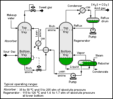
Modelling
The development of models for a better representation of real processes is the core of the further development of the simulation software. Model development is done through the principles of chemical engineering but also control engineering and for the improvement of mathematical simulation techniques. Process simulation is therefore a field where practitioners from chemistry, physics, computer science, mathematics, and engineering work together.
Efforts are made to develop new and improved models for the calculation of properties. This includes for example the description of
- thermophysical properties like vapor pressures, viscosities, caloric data, etc. of pure components and mixtures
- properties of different apparatus like reactors, distillation columns, pumps, etc.
- chemical reactions and kinetics
- environmental and safety-related data
There are two main types of models:
- Simple equations and correlations where parameters are fitted to experimental data.
- Predictive methods where properties are estimated.
The equations and correlations are normally preferred because they describe the property (almost) exactly. To obtain reliable parameters it is necessary to have experimental data which are usually obtained from factual data banks or, if no data are publicly available, from measurements.
Using predictive methods is more cost effective than experimental work and also than data from data banks. Despite this advantage predicted properties are normally only used in early stages of the process development to find first approximate solutions and to exclude false pathways because these estimation methods normally introduce higher errors than correlations obtained from real data.
Process simulation has encouraged the development of mathematical models in the fields of numerics and the solving of complex problems.
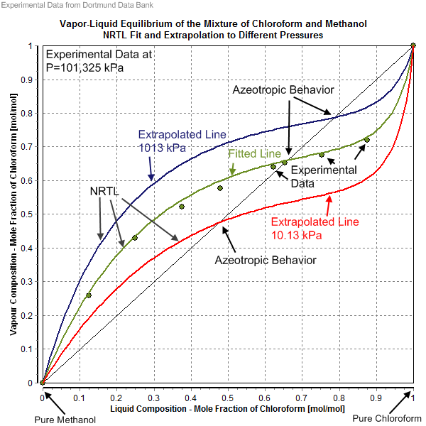
History
The history of process simulation is related to the development of the computer science and of computer hardware and programming languages. Early implementations of partial aspects of chemical processes were introduced in the 1970s when suitable hardware and software (here mainly the programming languages FORTRAN and C) became available. The modelling of chemical properties began much earlier, notably the cubic equation of states and the Antoine equation were precursory developments of the 19th century.
Steady state and dynamic process simulation
Initially process simulation was used to simulate steady state processes. Steady-state models perform a mass and energy balance of a steady state process (a process in an equilibrium state) independent of time.
Dynamic simulation is an extension of steady-state process simulation whereby time-dependence is built into the models via derivative terms i.e. accumulation of mass and energy. The advent of dynamic simulation means that the time-dependent description, prediction and control of real processes in real time has become possible. This includes the description of starting up and shutting down a plant, changes of conditions during a reaction, holdups, thermal changes and more.
Dynamic simulations require increased calculation time and are mathematically more complex than a steady state simulation. It can be seen as a multiple repeated steady state simulation (based on a fixed time step) with constantly changing parameters.
Dynamic simulation can be used in both an online and offline fashion. The online case being model predictive control, where the real-time simulation results are used to predict the changes that would occur for a control input change, and the control parameters are optimised based on the results. Offline process simulation can be used in the design, troubleshooting and optimisation of process plant as well as the conduction of case studies to assess the impacts of process modifications. Dynamic simulation is also used for operator training.
Simulation
A simulation is an approximate imitation of the operation of a process or system; that represents its operation over time.
Simulation is used in many contexts, such as simulation of technology for performance tuning or optimizing, safety engineering, testing, training, education, and video games. Often, computer experiments are used to study simulation models. Simulation is also used with scientific modelling of natural systems or human systems to gain insight into their functioning, as in economics. Simulation can be used to show the eventual real effects of alternative conditions and courses of action. Simulation is also used when the real system cannot be engaged, because it may not be accessible, or it may be dangerous or unacceptable to engage, or it is being designed but not yet built, or it may simply not exist.
Key issues in simulation include the acquisition of valid sources of information about the relevant selection of key characteristics and behaviors, the use of simplifying approximations and assumptions within the simulation, and fidelity and validity of the simulation outcomes. Procedures and protocols for model verification and validation are an ongoing field of academic study, refinement, research and development in simulations technology or practice, particularly in the work of computer simulation.
Classification and terminology
Historically, simulations used in different fields developed largely independently, but 20th-century studies of systems theory and cybernetics combined with spreading use of computers across all those fields have led to some unification and a more systematic view of the concept.
Physical simulation refers to simulation in which physical objects are substituted for the real thing (some circles use the term for computer simulations modelling selected laws of physics, but this article does not). These physical objects are often chosen because they are smaller or cheaper than the actual object or system.
Interactive simulation is a special kind of physical simulation, often referred to as a human in the loop simulation, in which physical simulations include human operators, such as in a flight simulator, sailing simulator, or driving simulator.
Continuous simulation is a simulation based on continuous time, rather than discrete time steps, using numerical integration of differential equations.
Discrete Event Simulation is a simulation based on discrete time steps, chosen to represent critical moments, while the values of the variables during each intervening period are not relevant.
Stochastic simulation is a simulation where some variable or process is subject to random variations and is projected using Monte Carlo techniques using pseudo-random numbers. Thus replicated runs with the same boundary conditions will each produce different results within a specific confidence band.
Deterministic simulation is a simulation which is not stochastic: thus the variables are regulated by deterministic algorithms. So replicated runs from the same boundary conditions always produce identical results.
Hybrid Simulation (sometime Combined Simulation) corresponds to a mix between Continuous and Discrete Event Simulation and results in integrating numerically the differential equations between two sequential events to reduce the number of discontinuities.
A stand alone simulation is a simulation running on a single workstation by itself.
A distributed simulation is one which uses more than one computer simultaneously, in order to guarantee access from/to different resources (e.g. multi-users operating different systems, or distributed data sets); a classical example is Distributed Interactive Simulation (DIS).
Parallel Simulation is executed over multiple processors usually to distribute the computational workload as it is happening in High-Performance Computing.
Interoperable Simulation where multiple models, simulators (often defined as Federates) interoperate locally, distributed over a network; a classical example is High-Level Architecture.
Modeling & Simulation as a Service where simulation is accessed as a service over the web.
Modeling, interoperable Simulation and Serious Games where Serious Games Approaches (e.g. Game Engines and Engagement Methods) are integrated with Interoperable Simulation.
Simulation Fidelity is used to describe the accuracy of a simulation and how closely it imitates the real-life counterpart. Fidelity is broadly classified as one of three categories: low, medium, and high. Specific descriptions of fidelity levels are subject to interpretation, but the following generalizations can be made:
- Low – the minimum simulation required for a system to respond to accept inputs and provide outputs
- Medium – responds automatically to stimuli, with limited accuracy
- High – nearly indistinguishable or as close as possible to the real system
Human in the loop simulations can include a computer simulation as a so-called synthetic environment.
Simulation in failure analysis refers to simulation in which we create environment/conditions to identify the cause of equipment failure. This was the best and fastest method to identify the failure cause.

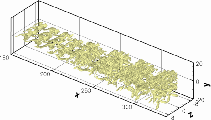
Computer simulation
A computer simulation (or « sim ») is an attempt to model a real-life or hypothetical situation on a computer so that it can be studied to see how the system works. By changing variables in the simulation, predictions may be made about the behaviour of the system. It is a tool to virtually investigate the behaviour of the system under study.
Computer simulation has become a useful part of modeling many natural systems in physics, chemistry and biology, and human systems in economics and social science (e.g., computational sociology) as well as in engineering to gain insight into the operation of those systems. A good example of the usefulness of using computers to simulate can be found in the field of network traffic simulation. In such simulations, the model behaviour will change each simulation according to the set of initial parameters assumed for the environment.
Traditionally, the formal modeling of systems has been via a mathematical model, which attempts to find analytical solutions enabling the prediction of the behaviour of the system from a set of parameters and initial conditions. Computer simulation is often used as an adjunct to, or substitution for, modeling systems for which simple closed form analytic solutions are not possible. There are many different types of computer simulation, the common feature they all share is the attempt to generate a sample of representative scenarios for a model in which a complete enumeration of all possible states would be prohibitive or impossible.
Several software packages exist for running computer-based simulation modeling (e.g. Monte Carlo simulation, stochastic modeling, multimethod modeling) that makes all the modeling almost effortless.
Modern usage of the term « computer simulation » may encompass virtually any computer-based representation.
Computer science:
In computer science, simulation has some specialized meanings: Alan Turing used the term « simulation » to refer to what happens when a universal machine executes a state transition table (in modern terminology, a computer runs a program) that describes the state transitions, inputs and outputs of a subject discrete-state machine. The computer simulates the subject machine. Accordingly, in theoretical computer science the term simulation is a relation between state transition systems, useful in the study of operational semantics.
Less theoretically, an interesting application of computer simulation is to simulate computers using computers. In computer architecture, a type of simulator, typically called an emulator, is often used to execute a program that has to run on some inconvenient type of computer (for example, a newly designed computer that has not yet been built or an obsolete computer that is no longer available), or in a tightly controlled testing environment (see Computer architecture simulator and Platform virtualization). For example, simulators have been used to debug a microprogram or sometimes commercial application programs, before the program is downloaded to the target machine. Since the operation of the computer is simulated, all of the information about the computer’s operation is directly available to the programmer, and the speed and execution of the simulation can be varied at will.
Simulators may also be used to interpret fault trees, or test VLSI logic designs before they are constructed. Symbolic simulation uses variables to stand for unknown values.
In the field of optimization, simulations of physical processes are often used in conjunction with evolutionary computation to optimize control strategies.
Simulation and manufacturing
Manufacturing represents one of the most important applications of simulation. This technique represents a valuable tool used by engineers when evaluating the effect of capital investment in equipment and physical facilities like factory plants, warehouses, and distribution centers. Simulation can be used to predict the performance of an existing or planned system and to compare alternative solutions for a particular design problem.
Another important goal of Simulation in Manufacturing Systems is to quantify system performance. Common measures of system performance include the following:
- Throughput under average and peak loads;
- System cycle time (how long it takes to produce one part);
- Utilization of resource, labor, and machines;
- Bottlenecks and choke points;
- Queuing at work locations;
- Queuing and delays caused by material-handling devices and systems;
- WIP storages needs;
- Staffing requirements;
- Effectiveness of scheduling systems;
- Effectiveness of control systems.
More examples of simulation
Biomechanics
An open-source simulation platform for creating dynamic mechanical models built from combinations of rigid and deformable bodies, joints, constraints, and various force actuators. It is specialized for creating biomechanical models of human anatomical structures, with the intention to study their function and eventually assist in the design and planning of medical treatment.
A biomechanics simulator is used to analyze walking dynamics, study sports performance, simulate surgical procedures, analyze joint loads, design medical devices, and animate human and animal movement.
A neuromechanical simulator that combines biomechanical and biologically realistic neural network simulation. It allows the user to test hypotheses on the neural basis of behavior in a physically accurate 3-D virtual environment.
Classroom of the future
The « classroom of the future » will probably contain several kinds of simulators, in addition to textual and visual learning tools. This will allow students to enter the clinical years better prepared, and with a higher skill level. The advanced student or postgraduate will have a more concise and comprehensive method of retraining—or of incorporating new clinical procedures into their skill set—and regulatory bodies and medical institutions will find it easier to assess the proficiency and competency of individuals.
The classroom of the future will also form the basis of a clinical skills unit for continuing education of medical personnel; and in the same way that the use of periodic flight training assists airline pilots, this technology will assist practitioners throughout their career.[citation needed]
The simulator will be more than a « living » textbook, it will become an integral a part of the practice of medicine.[citation needed] The simulator environment will also provide a standard platform for curriculum development in institutions of medical education.
Engineering, technology, and processes.
Simulation is an important feature in engineering systems or any system that involves many processes. For example, in electrical engineering, delay lines may be used to simulate propagation delay and phase shift caused by an actual transmission line. Similarly, dummy loads may be used to simulate impedance without simulating propagation and is used in situations where propagation is unwanted. A simulator may imitate only a few of the operations and functions of the unit it simulates. Contrast with: emulate.
Most engineering simulations entail mathematical modeling and computer-assisted investigation. There are many cases, however, where mathematical modeling is not reliable. Simulation of fluid dynamics problems often require both mathematical and physical simulations. In these cases the physical models require dynamic similitude. Physical and chemical simulations have also direct realistic uses, rather than research uses; in chemical engineering, for example, process simulations are used to give the process parameters immediately used for operating chemical plants, such as oil refineries. Simulators are also used for plant operator training. It is called Operator Training Simulator (OTS) and has been widely adopted by many industries from chemical to oil&gas and to the power industry. This created a safe and realistic virtual environment to train board operators and engineers. Mimic is capable of providing high fidelity dynamic models of nearly all chemical plants for operator training and control system testing.
Project management
Project management simulation is simulation used for project management training and analysis. It is often used as a training simulation for project managers. In other cases, it is used for what-if analysis and for supporting decision-making in real projects. Frequently the simulation is conducted using software tools.
Robotics
A robotics simulator is used to create embedded applications for a specific (or not) robot without being dependent on the ‘real’ robot. In some cases, these applications can be transferred to the real robot (or rebuilt) without modifications. Robotics simulators allow reproducing situations that cannot be ‘created’ in the real world because of cost, time, or the ‘uniqueness’ of a resource. A simulator also allows fast robot prototyping. Many robot simulators feature physics engines to simulate a robot’s dynamics.
Production
Simulation of production systems is used mainly to examine the effect of improvements or investments in a production system. Most often this is done using a static spreadsheet with process times and transportation times. For more sophisticated simulations Discrete Event Simulation (DES) is used with the advantages to simulate dynamics in the production system. A production system is very much dynamic depending on variations in manufacturing processes, assembly times, machine set-ups, breaks, breakdowns and small stoppages. There are lots of software commonly used for discrete event simulation. They differ in usability and markets but do often share the same foundation.
Weather
Predicting weather conditions by extrapolating/interpolating previous data is one of the real use of simulation. Most of the weather forecasts use this information published by Weather bureaus. This kind of simulations helps in predicting and forewarning about extreme weather conditions like the path of an active hurricane/cyclone. Numerical weather prediction for forecasting involves complicated numeric computer models to predict weather accurately by taking many parameters into account.
| Software | Developer | Applications | Operative system | License | URL |
| Advanced Simulation Library (ASL) | Avtech Scientific | Process data validation and reconciliation, real-time optimization, virtual sensing and predictive control | Windows, Linux, FreeBSD, Mac | open-source | [1] |
| APMonitor | APMonitor | Data reconciliation, real-time optimization, dynamic simulation and nonlinear predictive control | [2] | ||
| Apros | Fortum and VTT Technical Research Centre of Finland | Dynamic process simulation for power plants | Windows | Commercial | [3] |
| ASCEND | ASCEND | Dynamic process simulation, general purpose language | Windows, BSD, Linux | open-source | [4] |
| Aspen Custom Modeler (ACM) | Aspen Technology | Dynamic process simulation | Windows | Commercial | [5] |
| Aspen HYSYS | Aspen Technology | Process simulation and optimization | Windows | Commercial | [6] |
| Aspen Plus | Aspen Technology | Process simulation and optimization | Windows | Commercial | [7] |
| ASSETT | Kongsberg Digital | Dynamic process simulation | Windows | Commercial | [8] |
| BatchColumn | ProSim | Simulation and Optimization of batch distillation columns | Windows | commercial | [9] |
| BATCHES | Batch Process Technologies, Inc. | Simulation of recipe driven multiproduct and multipurpose batch processes for applications in design, scheduling and supply chain management | Linux | Commercial | [10] |
| BatchReactor | ProSim | Simulation of chemical reactors in batch mode | Windows | Commercial | [11] |
| BioSTEAM | Yoel Cortes-Pena & BioSTEAM Development Group | Design, simulation, and costing of biorefineries under uncertainty | Windows, Mac, Linux | open-source | [12] |
| CADSIM Plus | Aurel Systems Inc. | Steady-state and dynamic process simulation | Windows | Commercial | [13] |
| ChromWorks | YPSO-FACTO | Chromatographic process design, simulation & optimization | Windows | Commercial | [14] |
| CHEMCAD | Chemstations | Software suite for process simulation | Windows | Commercial | [15] |
| CHEMPRO | EPCON | Process Flow Simulation, Fluid Flow Simulation, & Process Equipment Sizing | Windows | Commercial | [16] |
| Clearview | Mapjects | Dynamic Asset BIM process simulation and optimization | Windows & Debian Linux | ||
| Cycad Process | CM Solutions | Process simulation and drawing package for minerals and metallurgical fields | Windows | Commercial, Free for academic use | [17] |
| Cycle-Tempo | Asimptote | Thermodynamic analysis and optimization of systems for the production of electricity, heat and refrigeration | [18] | ||
| COCO simulator + ChemSep | AmsterCHEM | Steady state process simulation based on CAPE-OPEN Interface Standard | Windows | Free | [19] [20] |
| D-SPICE | Kongsberg Digital | Dynamic process simulation | Windows | Commercial | |
| Design II for Windows | WinSim Inc. | Process simulation | [21] | ||
| Distillation expert trainer | ATR | Operator training simulator for distillation process | [22] | ||
| Dymola | Dassault Systèmes | Modelica-based dynamic modelling and simulation software | Windows, Linux | Commercial | [23] |
| DynoChem | Scale-up Systems | Dynamic process simulation and optimization | Windows | Commercial | [24] |
| DYNSIM | AVEVA | Dynamic process simulation | Windows | Commercial | |
| DWSIM | Daniel Medeiros, Gustavo León and Gregor Reichert | Process simulator | Windows, Linux, macOS, Android, iOS | open-source (Windows/Linux/macOS), free + in-app purchases (Android/iOS) | [25] |
| EMSO | ALSOC Project | Modelling, simulation and optimisation, steady state and dynamic, equation oriented with open source models | Windows, Linux | ALSOC License | [26] |
| EQ-COMP | Amit Katyal | Vapor Liquid Equilibrium Software | SAAS | [59] | |
| FlowTran | FlowTran | Transient single phase pipeline simulation | Commercial | [27] | |
| GAMS | GAMS | General Algebraic Modeling System (GAMS) | Windows, Linux, Mac OS, Solaris | Commercial | [28] |
| gPROMS | PSE Ltd | Advanced process simulation and modelling | [29] | ||
| HSC Sim | Outotec Oyj | Advanced process simulation and modelling, Flowsheet simulation | Windows | [30] | |
| HYD-PREDIC | Amit Katyal | Flow Assurance Software | |||
| HYDROFLO | Tahoe Design Software | Piping System Design with Steady State Analysis | Windows | Free Academic, Standard Commercial | [31] |
| Indiss Plus® | Corys | Dynamic process simulator for hydrocarbons, chemicals | [32] | ||
| ICAS | CAPEC | Integrated Computer-Aided System | [33] | ||
| IDEAS | Andritz Automation | Dynamic simulator for pulp, oil sands, potash, and hard rock mining | Windows | Commercial | [34] |
| iiSE Simulator | iiSE company | Equation oriented chemical process simulator and optimizer | Windows, Linux | Commercial | [35] |
| ITHACA | Element Process Technology | Dynamic chemical process simulator | Windows | [36] | |
| JADE | GSE Systems | Dynamic process simulation | Windows | Commercial | |
| JModelica.org | Modelon AB | Process simulation | Windows, Linux, Mac OS | open-source | |
| K-Spice | Kongsberg Digital | Dynamic process simulation | Windows | Commercial | [37] |
| LedaFlow | Kongsberg Digital | Transient multiphase pipeline simulation | Windows | Commercial | [38] |
| LIBPF | simevo | C++ LIBrary for process flowsheeting | |||
| METSIM | Metsim International | General-purpose dynamic and steady state process simulation system | Windows | [39] | |
| Mimic Simulation Software | MYNAH Technologies | First-principles dynamic simulator built for software acceptance testing and operator training systems | [40] | ||
| Mobatec Modeller | Mobatec | Advanced Dynamic (Steady-State) Process Modelling Environment | Windows | [41] | |
| NAPCON ProsDS | Neste Engineering Solutions Oy | Dynamic process simulation | Windows | [42] | |
| OLGA | Schlumberger | Transient multiphase pipeline simulation | Windows | Commercial | [43] |
| OLI Analyzer | OLI Systems, Inc. | Chemical phase equilibrium simulation featuring electrolytes | Windows | Commercial | [44] |
| Omegaland | OMEGA Simulation | Dynamic process simulation | Windows | Commercial | [45] |
| OptiRamp | Statistics & Control, Inc. | Real-time Process Simulation and Optimization, Multi variable Predictive Control | Windows | Commercial | [46] |
| OpenModelica | Open-Source Modelica Consortium | General purpose simulation | open-source | ||
| PD-PLUS | Deerhaven Technical Software | Steady-State Modeling of Chemical, Petrochemical, and Refining Processes | Windows | Commercial | [47] |
| PIPE-FLO Professional | Engineered Software Inc. | Piping System Simulation and Design | Windows | Commercial | [48] |
| PIPEFLO | Schlumberger | Steady state multiphase flowline simulation | Windows | Commercial | |
| PIPESIM | Schlumberger | Steady state multiphase flowline simulation | Windows | Commercial | |
| PEL Suite | PEL Software | Steady state process simulation | Windows | Commercial | [49] |
| Petro-SIM | KBC Advanced Technologies | Dynamic process simulation | Windows | Commercial | [50] |
| PETROX | Petrobras | General Purpose, Static, Sequential-Modular Process Simulator | Windows | internal users only | |
| Power Plant Simulator & Designer | KED GmbH | Basic Engineering and Dynamic process simulation for power plants | Windows | Commercial | [51] |
| Process Studio | Protomation | Simulation Suite for Modeling, Engineering & Training | Windows | Commercial | [52] |
| Prode Properties | Prode Software | Thermodynamic Library, Properties of pure fluids and mixtures, Multi phase Equilibria + process simulation | Windows, Linux, Android | Free version + commercial versions | [53] |
| Prode simulator | Prode Software | Process Simulator | Windows | commercial | [54] |
| ProMax | Bryan Research & Engineering | Process simulator capable of modeling oil & gas plants, refineries, and many chemical plants | Windows | [55] | |
| ProMax / TSWEET | Bryan Research & Engineering | Retired process simulators now incorporated in ProMax | |||
| ProPhyPlus | ProSim | Thermodynamic calculation software | Windows | commercial | [56] |
| ProSec | ProSim | Simulation of brazed plate fin heat exchangers | Windows | commercial | [57] |
| ProSim DAC | ProSim | Dynamic adsorption column simulation | Windows | commercial | [58] |
| ProSim HEX | ProSim | Heat Exchangers Simulation | Windows | commercial | [59] |
| ProSimPlus | ProSim | Steady-state simulation and optimization of processes | Windows | commercial | [60] |
| ProSimulator | Sim Infosystems | Process and Power plant simulation | Windows | [61] | |
| Pro-Steam | KBC Advanced Technologies | ||||
| PRO/II | AVEVA | Steady state process simulation | Windows | Commercial | [62] |
| ROMeo | AVEVA | Process optimization | Windows | Commercial | |
| RecoVR | VRTech | ||||
| REX | Optience | Reactor Optimization and Kinetic Estimation | Windows | [63] | |
| SimCentral | AVEVA | Steady state, Fluid flow and Dynamic process simulator. | Windows | Commercial | [64] |
| SimCreate | TSC Simulation | Real time, first principle and generic operator training simulations, plant specific emulations and OPC for live plant connections. | Windows | Commercial | [65] |
| Simulis Thermodynamics | ProSim | Mixture properties and fluid phase equilibria calculations | commercial | [66] | |
| SolidSim (Now in Aspen Plus) | SolidSim Engineering GmbH | Flowsheet simulation of solids processes | [67] | ||
| SPEEDUP | Aspen Technology | Dynamic process simulation | Unix, Windows | Commercial | |
| SuperPro Designer | Intelligen | [68] | |||
| SysCAD | KWA Kenwalt Australia | Process simulation | Windows | [69] | |
| UniSim Design Suite | Honeywell | Process simulation and optimization | Windows | Commercial and Academic | [70] |
| UniSim Competency Suite | Honeywell | Opertator Competency Management and Training | Windows | Commercial and Academic | [71] |
| Usim Pac | Caspeo | Steady-state simulator for the mineral industry, biorefineries and waste treatment | Windows | Commercial | [72] |
| Virtuoso | Wood PLC | Multiphase dynamic process simulator for oil & gas production | Windows | Commercial | [73] |
| VMGSim | Schlumberger | Steady state simulation, dynamic process simulation, transient multiphase flowline simulation | Windows | Commercial | [74] |
| Wolfram SystemModeler | Wolfram Research | Windows, Mac, Linux | [75] |
